Author Topic: Stuart No. 4 Build  (Read 29044 times)

Offline smfr

  • Jr. Member
  • **
  • Posts: 33
  • Country: us
Re: Stuart No. 4 Build
« Reply #25 on: July 18, 2012, 11:54:33 AM »
[Moved from homemodelenginemachinist.com]
I left the piston rod gland set up in the rotary table last night, so couldn't resist drilling the 7 holes (capstan holes?) tonight.

I put an MT2 collet in the center hole of the rotary table, holding a spare piston rod (1/4"), so could use that to center the bottom cylinder cover with piston rod gland on the table, and allowed me to clamp the cylinder cover:


I did have to move the clamps around for the different holes though. I did 7 holes, 51° 26" apart, counting turns on the rotary table handle (hmm, could I have used the dividing plate? Not sure if it does 7's), with a 1/16" drill.

All done, lightly countersunk the holes by hand:


I did a quick assembly of the engine with the piston, and even without the piston rings, or any bolts holding stuff together, was getting some reasonable compression in the cylinder. This is quite exciting! Of course it probably means that the cast iron piston is a tad oversized; I think I want about 0.002" of clearance for a cast iron piston in a cast iron cylinder, with cast iron rings?

I think I'll work on the valve chest and value parts next. The eccentric strap is probably the most tricky part left; I'm going to make the simple value fittings first as practice, get it all working, and then do the reversing parts later.

Offline smfr

  • Jr. Member
  • **
  • Posts: 33
  • Country: us
Re: Stuart No. 4 Build
« Reply #26 on: July 18, 2012, 11:55:51 AM »
[Moved from homemodelenginemachinist.com]
I worked on the valve chest today, which seemed to be a bit slow going.

First step after marking up: square up the inside a bit. No critical dimensions here, just need room for the valve to move.


This kit is old enough that the valve guide is cast into the valve chest; the newer models have a brass fitting that you machine separately, then screw in. I suppose that avoids having to drill deep through the valve chest and adds some brass bling, but I think I prefer the old way.

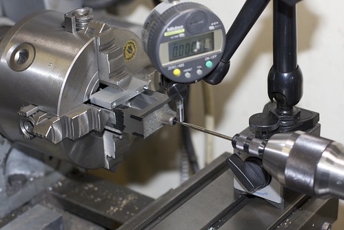
Anyhoo, the valve chest was chucked up in the 4-jaw with some backing, and a wiggler and indicator used to center on the punch mark at the end of the valve guide:


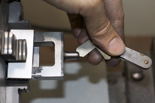
I started with an HSS ground tool bit because of the interrupted cut, and to take the crust off the casting. Towards the end I switched to a carbide insert tool, which does risk getting chipped because of the interrupted cut, but actually performed fine. After a bit of turning we're close. Both radii were done "freehand" and cleaned up with files. Here I'm using a radius gauge to check the shaping on the end:


and in this photo the neck radius still needs some cleanup. With a bit more work it's almost done:


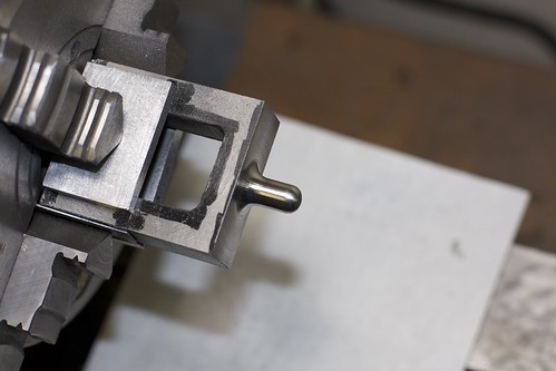
but I still need to get rid of some tool marks around the base.

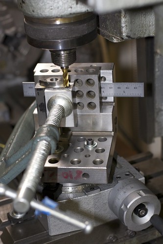
Now it's time to drill and ream for the valve rod. The angle plate on its side serves as a useful way to hold the casting square (the sides have already been machined), and we locate on the punch mark:


The top end is drilled then reamed 3/16", and the bottom end has a 1/8" hole reamed into the valve guide. Luckily, for the lower hole, I had an extra long drill that I'd picked up at a yard sale or flea market a while back, but of course it wandered all over the place when trying to enter the bottom of the casting.

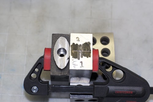
My solution was to clamp a block of Al inside the valve check, switch back to the stubby drill then drill through that to form a guide for the longer drill.


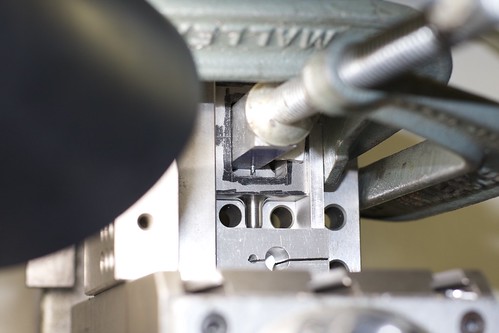
This worked nicely; with the block still clamped, it acted as a guide for the longer drill which no longer wandered, and I was able to complete the lower hole, then ream 1/8".

The upper hole was also opened up to 3/8" using a small boring tool; the valve rod gland fits into this.

I now pondered long and hard about how to do the profiling on the lower side of the valve chest. I guesstimated from the plans that the curves have a radius of 1", then blend into a radius around the bolt holes. To machine the curves, my options were the rotary table (setup too hard on my tiny table), the faceplate (easier setup, but hard to control the radius from the center), and the 4-jaw. After hatching a cunning plan to get the right offsets, the 4-jaw won.

I used a scrap block of Al as a simple fixture, and computed and marked out two punch marks:


When the fixture is located in the 4-jaw with the appropriate punch mark centered, I know that if the valve chest is clamped against the fixture the right way around, I'll hit that 1" radius for that side of the valve chest.

Here's the 4-jaw setup, with the fixture clamped in the middle, and the casting held by just one jaw.


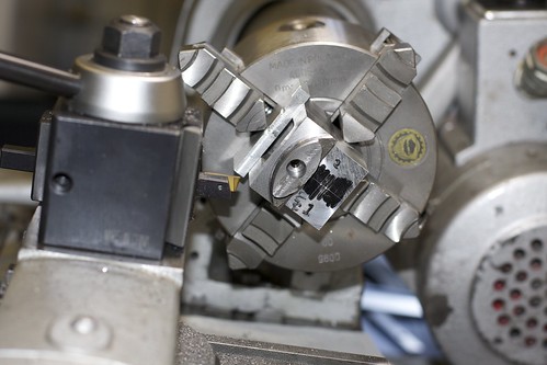
Not an ideal way to hold something in the 4-jaw, but the setup was pretty rigid so I wasn't too worried. I've already centered the fixture on punch mark no. 1, then I had to fiddle around a bit to get the casting lined up (using a square to align the chuck, and a height gauge locating on a drill bit which was a tight fit into the reamed hole). I've mostly finished one side in this photo.

After doing both sides it looks like an eye :D


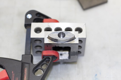
I didn't quite get things lined up, so there's a bit of a step where the machining of the two sides comes together; I'll have to clean that up by filing later.

Back onto the mill, using the angle plate setup again, to locate, drill and tap the holes for the gland screws:


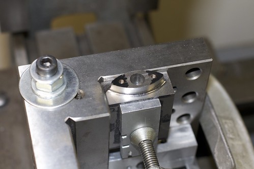
Now another crazy setup ;D I wanted to round off the corners of the "eye" shape on the rotary table. The only way I could figure out how to hold it was on the angle plate:


There's a little rotary table under there somewhere! Usual rotab drill: locate the rotary table under the mill and clamp it down. Set up the part on the table, also centered (I used a drill bit dropping into one of those tapped holes for location). Now use the carriage to adjust the radius being cut.

I don't have any ball-end mills of the right radius, so I milled a few steps, then cleaned up with a file. Here we are, one side done:


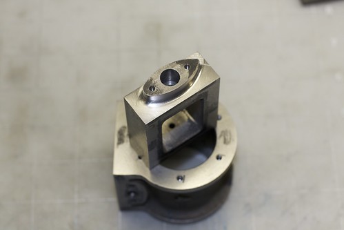
This part is on the underside of the valve chest, so I don't have to get too crazy with finishing, and it might even be painted. I can never decide whether to paint valve chests!

Tomorrow I hope to finish the profiling here, mill the chest down to thickness, do the valve chest cover, and drill and tap for the studs that hold the valve chest to the cylinder.

Offline smfr

  • Jr. Member
  • **
  • Posts: 33
  • Country: us
Re: Stuart No. 4 Build
« Reply #27 on: July 18, 2012, 11:56:23 AM »
[Moved from homemodelenginemachinist.com]
Another Sunday, another day in the shop :)

I got the other side of the valve chest gland profile rounded off, but here's what happens when you go a bit too far on the rounding table:


I should be able to take it out by filing.

I milled the valve chest down to about the right thickness; the outer side is non-critical, and I left is slightly thick because otherwise I start running into the radii for the valve guide and the gland thingy.

Now the valve cover gets a cleanup, first with an old end mill of unknown sharpness, to get through the crust, and then with a nice sharp one on a finish pass:


Then I did something that I might regret, which is to clean up the center indentation. Not having any ball-end mills, I used a little carbide burr that came with the Dremel:


It did the job OK, but I'll have to file away some of the machining marks. I'll need some riffler files to get into the concavity. I say I might regret it because it might make the cover look too too machined, and not like a casting. I guess it depends on how I paint it.

While marking out the valve cover for final size, I also marked out the stud holes:


It's another crazy setup! :D I wanted to drill the cover, valve chest and piston all at the same time to ensure that all the stud holes lined up. So I came up with a setup, using the angle plate as a backing, a 1-2-3 block on each side between which the parts could be clamped, and some spacers at the back to align the top edges of the parts:


Some cardboard takes up the slight differences in thickness between the parts. I set this up so that, if need be, I could repeatably remove and replace the valve chest and cover to drill the piston itself. It turns out I didn't need to do that. One problem with this setup was that the holes are pretty deep, so the drill chuck could hit the 1-2-3 blocks. I had to use a full length drill bit (slightly undersize for the tapping size) to go all the way down into the piston. This worked fine, but I did manage to drill through into the exhaust hole. :-\ Oh well, that's not under pressure so it shouldn't be a problem.

The holes in the chest and cover were then opened up to clearance size (#27) with the part held in a screwless vise, held by hand. Then the holes in the piston were drilled to tapping size (#33), the 4BA taper tap started in the mill by hand, then tapping completed using a tap wrench.


Always a bit nerve-wracking on a part into which many hours have gone, but it went fine.

Now for a test fit:


All the studs look straight, which is a good sign. And the valve chest and cover fit nicely over the studs, so my drilling in-place seems to have paid off.

To end the day, some mock assembly pictures to see how everything fits together:


I have yet to drill the steam hole in the valve chest. I see some engines with steam and exhaust on one side (keep all the pipes together?), and some with steam in one side, exhaust the other. I'm not sure which I want yet.

Simon

Offline Brass_Machine

  • Administrator
  • Hero Member
  • *****
  • Posts: 5504
  • Country: us
Re: Stuart No. 4 Build
« Reply #28 on: July 18, 2012, 12:06:48 PM »
Hi Simon  :wave:

1st, Welcome to the collective :borg:
2nd, this has to be one of the fastest builds I have ever seen  :lol:

Nice work so far! I like seeing the setups on some of your machining steps. Definitely helps someone who is new.

Eric
Science is fun.

We're all mad here. I'm mad. You're mad.

Offline dsquire

  • In Memoriam
  • Hero Member
  • *****
  • Posts: 2275
  • Country: ca
  • Kitchener, Ontario, Canada
Re: Stuart No. 4 Build
« Reply #29 on: July 18, 2012, 07:45:07 PM »
Simon

Welcome to MadModder. We are glad to see you here and look forward to your participation in the various forums. I like the work that you are doing.

Cheers  :beer:

Don
Good, better, best.
Never let it rest,
'til your good is better,
and your better best

Offline kwackers

  • Sr. Member
  • ****
  • Posts: 356
Re: Stuart No. 4 Build
« Reply #30 on: July 19, 2012, 04:02:21 AM »
Well done on the No 4 build, I'm also building one (and have castings for a second - both bought at the local engineering club auction!)

Regarding the location of the steam pipes iirc (i.e. check for yourself) doesn't the location of one of the brackets for the reversing gear dictate which side this should be on? (Obviously you could make a mirror of the relevant parts to get around this).

Currently mine is stopped at the reversing eccentrics, annoyingly it turns out the shaft cast onto them wasn't cast straight and I can't make the part as drawn, so I'm going to cut the shaft off and make up a mild steel shaft so my eccentrics will be 3 parts.

Offline mzt

  • Jr. Member
  • **
  • Posts: 88
  • Country: it
Re: Stuart No. 4 Build
« Reply #31 on: July 19, 2012, 04:52:48 AM »
Quote
2nd, this has to be one of the fastest builds I have ever seen  :lol:


- Eric,
I could bring two engines close to completion in the same time !!  :D 
Wanna see?


- Simon,
I've been following Your inspiring build: You're definitely doing a great job.

Marcello


Offline smfr

  • Jr. Member
  • **
  • Posts: 33
  • Country: us
Re: Stuart No. 4 Build
« Reply #32 on: July 19, 2012, 11:52:56 AM »
Regarding the location of the steam pipes iirc (i.e. check for yourself) doesn't the location of one of the brackets for the reversing gear dictate which side this should be on? (Obviously you could make a mirror of the relevant parts to get around this).

Oh good point, I hadn't thought to check relative to the reversing gear. I've already done the exhaust hole on the right side of the cylinder, so I hope that's not wrong :)

Simon

Offline NickG

  • Madmodder Committee
  • Hero Member
  • *****
  • Posts: 1890
Re: Stuart No. 4 Build
« Reply #33 on: July 19, 2012, 02:25:24 PM »
Hi Simon, looks like I'll be following over here then! Looking forward to the rest ... :thumbup:
Location: County Durham (North East England)

Offline kwackers

  • Sr. Member
  • ****
  • Posts: 356
Re: Stuart No. 4 Build
« Reply #34 on: July 19, 2012, 03:28:04 PM »
Just had a look at mine and the bracket that fits to the right of the steam box (as you look directly at it) would foul the steam fitting if it were on that side...
My plans are dated 1954 though, so perhaps it's changed!

I guess if it's the case then you can either mirror the reversing gear or just tap all the holes you've made and loctite some threaded rod in then machine/file it flat before sticking the steam fitting on the other side (assuming you're painting the steam chest).

Offline saw

  • Hero Member
  • *****
  • Posts: 1003
  • Country: se
  • lucky amateur
    • Svenssons AckordsWerkstad
Re: Stuart No. 4 Build
« Reply #35 on: July 19, 2012, 04:43:55 PM »
 :wave: Hi and welcome, I have been reading the whole project and I am very inpressed   :bow: :bow: :bow:
_________________________
Greetings / Benni
http://myprojecty.wordpress.com/category/steam-engine/

Offline krv3000

  • Hero Member
  • *****
  • Posts: 2183
  • Country: gb
Re: Stuart No. 4 Build
« Reply #36 on: July 19, 2012, 06:33:50 PM »
hi smrf thats brill keep it up

Offline Don1966

  • Jr. Member
  • **
  • Posts: 8
  • Country: us
Re: Stuart No. 4 Build
« Reply #37 on: July 19, 2012, 11:40:32 PM »
Hi Simon I still here following, I have made the move also. Waiting to see it complete.

Don
How many times I did that?

Offline smfr

  • Jr. Member
  • **
  • Posts: 33
  • Country: us
Re: Stuart No. 4 Build
« Reply #38 on: July 20, 2012, 01:59:48 AM »
Just had a look at mine and the bracket that fits to the right of the steam box (as you look directly at it) would foul the steam fitting if it were on that side...
My plans are dated 1954 though, so perhaps it's changed!

I guess if it's the case then you can either mirror the reversing gear or just tap all the holes you've made and loctite some threaded rod in then machine/file it flat before sticking the steam fitting on the other side (assuming you're painting the steam chest).

Darn. My plans are from 1953 (I think), and that's what I've been following. Note that I'm talking about the exhaust port on the cylinder, not the steam intake on the valve chest.

I'd hate to have to mirror the whole reversing gear, though I guess it would make for a unique engine  :D

This one seems fine with the exhaust hole on the right though:


as does this 10V:


so I think I'm OK.

Simon

Offline kwackers

  • Sr. Member
  • ****
  • Posts: 356
Re: Stuart No. 4 Build
« Reply #39 on: July 20, 2012, 04:46:27 AM »
Ah - I *presumed* you were talking about the inlet on the chest so you'll be fine!
My exhaust is on the right and the inlet on the left, it's only a problem if you move the inlet over to the right!
(I don't think the exhaust is an issue, in theory it could be on either side)

Offline grayone

  • Jr. Member
  • **
  • Posts: 38
  • Country: 00
Re: Stuart No. 4 Build
« Reply #40 on: July 21, 2012, 07:36:04 AM »
From post #3
I then glued the two together, planning to turn the bosses. However, I realized that I had no true surface I could use to ensure that the join was aligned the turning axis, and in the center. So after some application of heat to undo the Superglue, I used a chuck spider in the 4-jaw to put a small flat on top of each bearing, with the bearings having the same thickness:

What is a "chuck spider" and what is it used for and why -  :scratch: - sorry if this is a dumb question but never heard this term before

Graham
Growing old is mandatory, growing up is optional

Offline PekkaNF

  • Hero Member
  • *****
  • Posts: 2523
  • Country: fi
Re: Stuart No. 4 Build
« Reply #41 on: July 21, 2012, 08:46:49 AM »
From post #3
I then glued the two together, planning to turn the bosses. However, I realized that I had no true surface I could use to ensure that the join was aligned the turning axis, and in the center. So after some application of heat to undo the Superglue, I used a chuck spider in the 4-jaw to put a small flat on top of each bearing, with the bearings having the same thickness:

What is a "chuck spider" and what is it used for and why -  :scratch: - sorry if this is a dumb question but never heard this term before

Graham

Seemed to be that cheese plate between chuck face and part. Like this:
http://www.cnccookbook.com/img/OthersProjects/CNCBusiness/LatheSpiderDrawing.jpg
Most likely used a back stop to stop part on right place to make multiple parts of same length. Bit like a back stop.

Then sometimes it is sort of "spreader" to preload jaws for truing the jaws - takes up slack to same direction as when in use.

And then again I have heard it used at the back of the spindle to center longish piece from back end:
http://img.photobucket.com/albums/v654/300sniper/rifle%20tools/barrelthread2.jpg

And same thing at the nose of spindle is sometimes called a "pot chuck".

After this explanation I have confused even myself :D

Pekka

Offline smfr

  • Jr. Member
  • **
  • Posts: 33
  • Country: us
Re: Stuart No. 4 Build
« Reply #42 on: July 24, 2012, 12:18:50 AM »
Here's a page that explains this style of chuck spider:

http://www.neme-s.org/Spider.htm

Simon

Offline mackye

  • Newbie
  • *
  • Posts: 1
Re: Stuart No. 4 Build
« Reply #43 on: October 02, 2012, 01:45:56 AM »
hi simon,

hows the engine progressing??

i followed this thead over from HMEM as its such a beautiful build!!!

mackye