Author Topic: Making tools to mend tools to work on tools  (Read 17159 times)

Offline RichardShute

  • Jr. Member
  • **
  • Posts: 85
Making tools to mend tools to work on tools
« on: February 12, 2011, 07:36:51 PM »
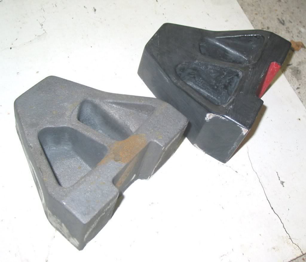
When I got my milling machine it was missing the overarm bearing for the outboard end of a horizontal arbor. Mostly I use the machine as a vertical, but it has always irritated me that I haven't got 'the full set' with the machine and as a two year-long scan of fleaBay failed to dig one up I decided to bite the bullet and make one. I made a pattern by laminating some 1" plywood to get a block thick enough. This was a mistake as changes in temperature and humidity, even after painting it, made the laminations move about and show up. Again and again and again..... sand it smooth, (re)paint it wait two days and the laminations are sticking out like a sore thumb. It eventually got less mobile, by which time it probably had 10 or 12 coats of paint and sanding. It was less than ideal, but adequate so I took it in and had it cast at a local foundry. Not exactly cheap, but about what I would have paid had one turned up for sale so not cripling either. But obviously I need to machine it. Here's the pattern and casting side by side.


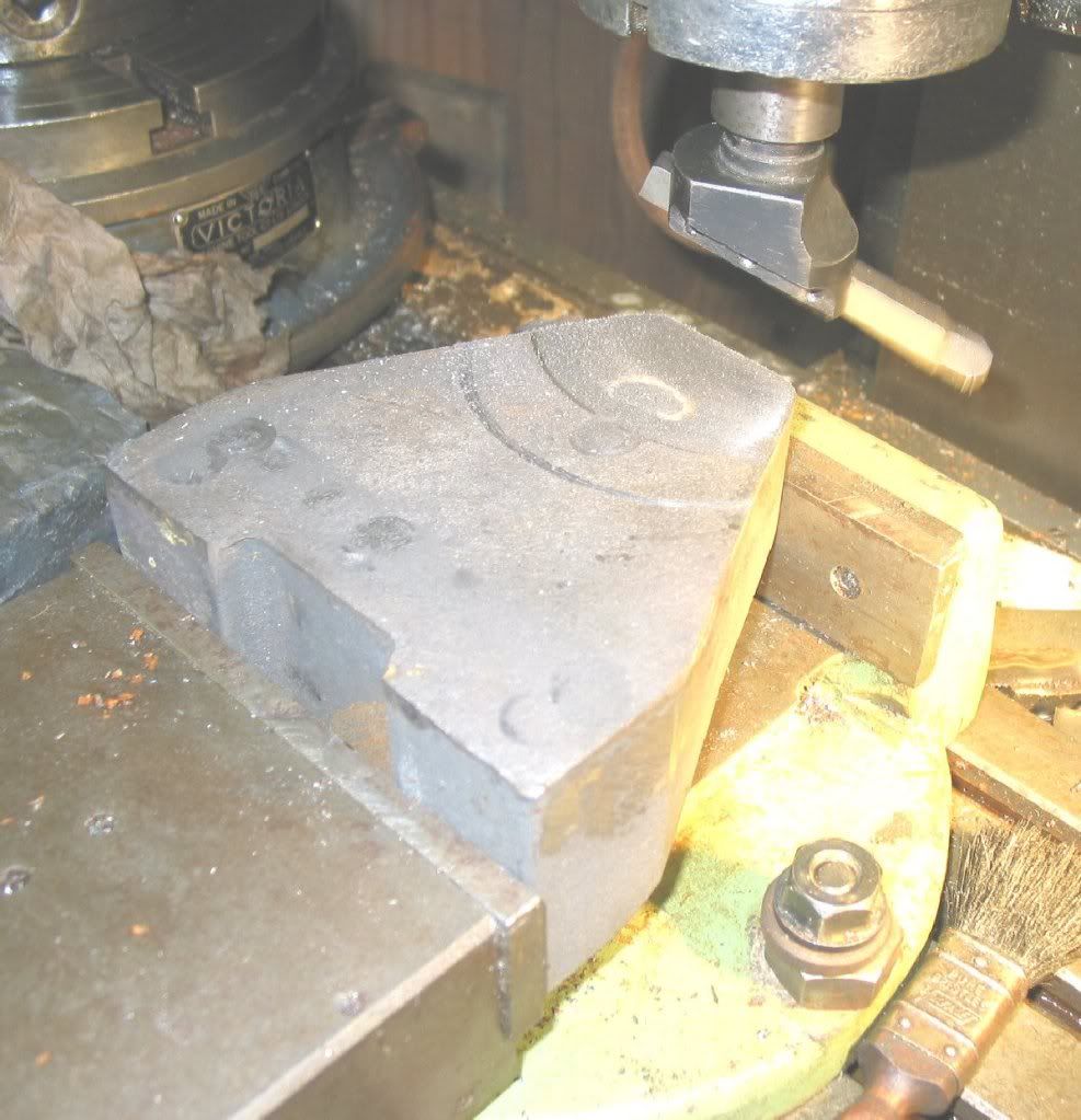
The first thing to do is get a reference so I took a swipe across the front face with a fly cutter. It's not a hugely important surface, but it's an easy one to give me a reasonable surface to mount it and measure from for.


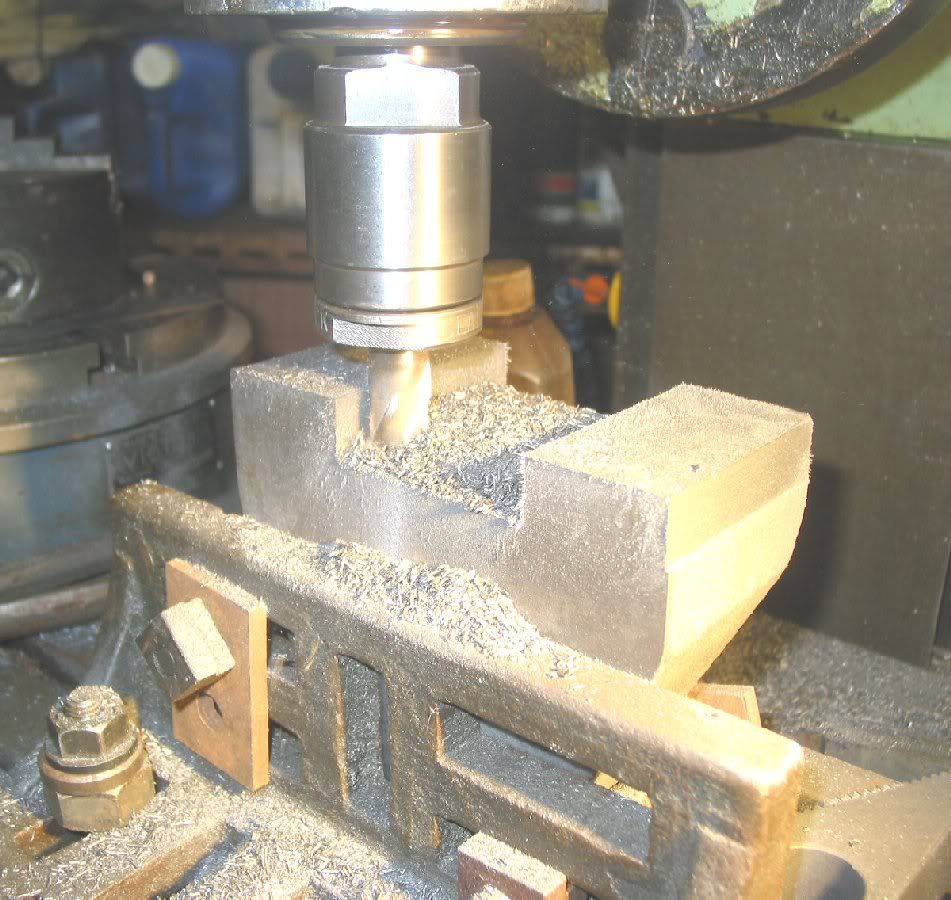
I also took a cut along what will be the top face as a starting point for setting the casting up on an angle plate. Then hogged out the bulk of where the dovetail will be.


as well as taking a cleaning cut down the side of the block for alignment and setting up later.


The dovetails will be hand scraped to match the slides on the machine, but unfortunately I had assumed they were 60deg which would have been easy to use a dovetail cutter to get close, but in fact on measuring them, they are 55deg, strange but true. So I decided to cut them on the shaper.
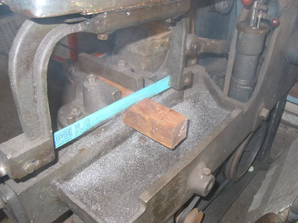
Start by making a gauge to check the bearing block as once it is big enough to fit on the machine it's already too big and adjusting the fit will only make it more too biggerer. I grabbed a bit of 2x2 sq steel and set the donkey saw to work on that while I ground up a tool for the shaper.


It needs to be less than 55deg between the flanks so that I can cut the dovetail and still have some side clearance. No particular angle was set, I just eye-balled it up to be less than the dovetail by probably 8~10 deg.

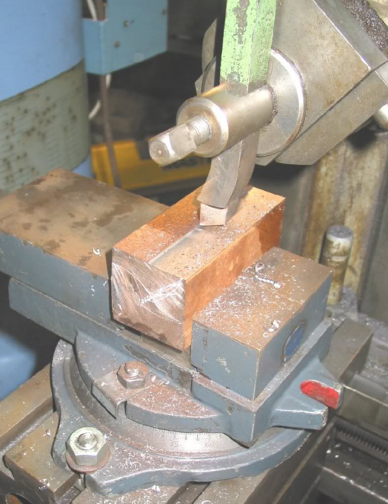
The saw's done its job and now I set the vice straight on the shaper and put the blank up to take a lick off the top to clean it up and give me a reference.


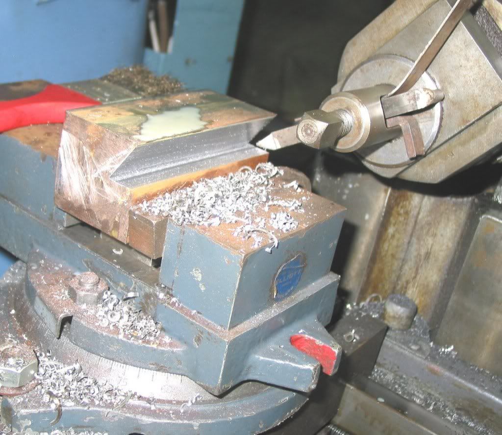
and then set up the fine tipped tool for the cutting the vee. As is usual it took far longer to set it all up than to actually do the job. The shaper is a bit small for the job, not in terms of stroke, but the necessary side movement to get the tool to the side of the block. I did not want to put the vee in the top of the block as I'm essentially lazy and the machine has no powered vertical feed, but does have a powered horizontal. This makes it much easier to get a nice finish on at least one side of the vee. I roughed out the groove using the table vertical slide and advanced the tool slide down and in. The great thing with shapers is they eat metal quickly and yet still give a good finish. Once the bulk of the groove was clear, I re-set the table support leg and took a finer cut across the flat of the groove. Then backed the tool slide up and took a finishing cut down the angled face with the hand feed on the tool slide, set at an angle (ie 90-55 = 35deg).


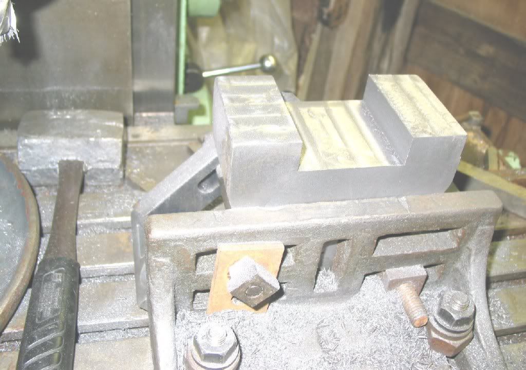
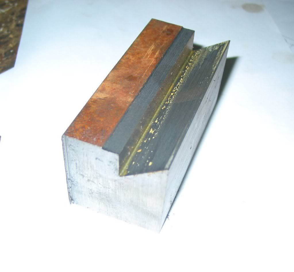
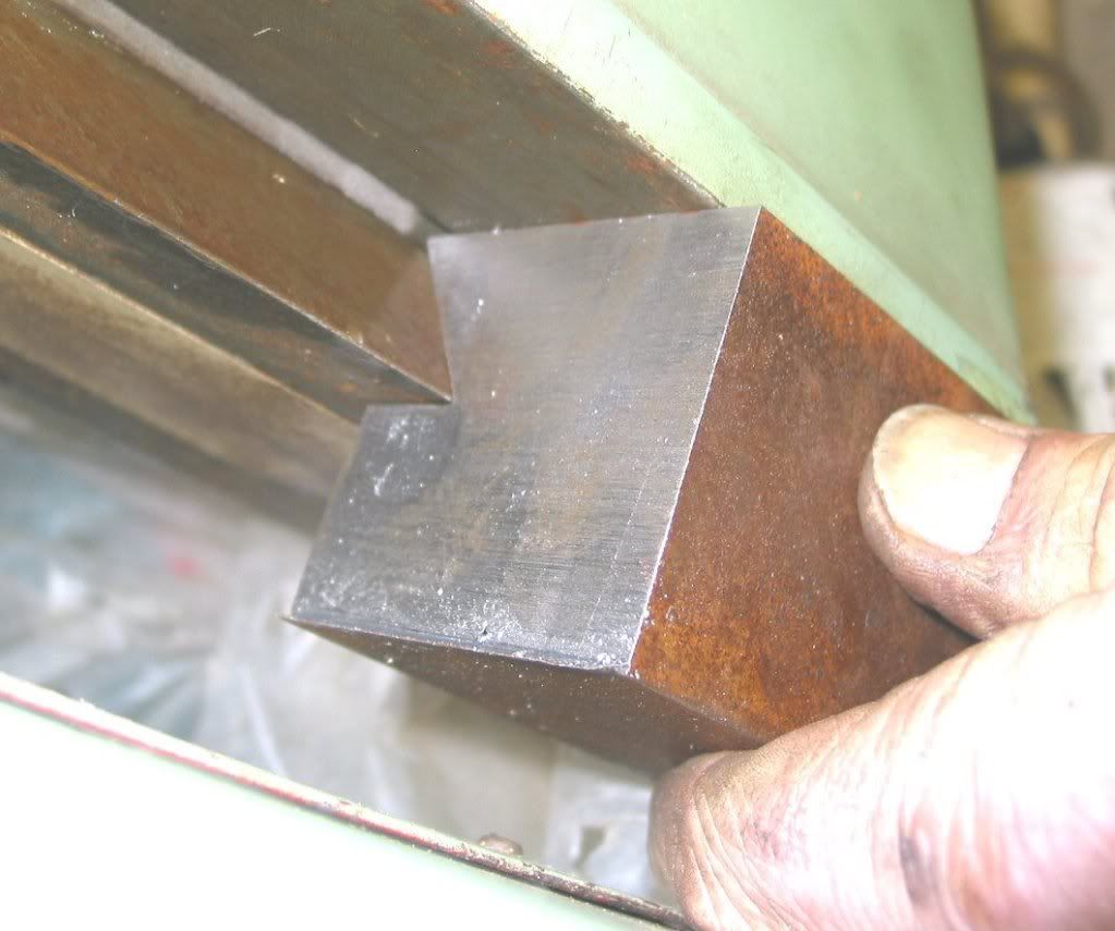
And here's the finished gauge blank.


A quick trial fit onto the dovetail and it is close. No the dovetail is not rusty, just an oil stain, the camera is not very flattering.


I've not blued it yet, but I don't think it will be too far off. Once it is right, I will take a swipe off the 'back' to true the face to the vee and then cut it in half. I can then use the two parts inside the dovetail as yet to be made on the top of the bearing block and measure between them to get a indication of the width of the dovetail. Yes, I could do that by measureing between rollers, but I need an angle gauge to get the flanks right anyway, so I might as well use the same gauge for both jobs.

It's a bit of a background project this, so don't hold you breath for the next bit, but I will get round to it..... sometime.

Richard
For every fool-proof solution, there is a fool greater than the proof

Offline Bogstandard

  • Bogs Group
  • Hero Member
  • *****
  • Posts: 1107
Re: Making tools to mend tools to work on tools
« Reply #1 on: February 12, 2011, 08:36:12 PM »
I fully understand your problem about the angles. My machine has the 55 degree dovetail, and when I bought a horizontal arbor at the right price, that came wih a 50 deg dovetail.

Not wanting to change the original item, I came up with a solution of a pair of converter blocks that did the job perfectly.

http://madmodder.net/index.php?topic=2083.0

I am sure you will get your problem solved with very little trouble.


Bogs
If you don't try it, you will never know if you can do it.

Location - Crewe, Cheshire

Skype - bandit175

Offline RichardShute

  • Jr. Member
  • **
  • Posts: 85
Re: Making tools to mend tools to work on tools
« Reply #2 on: March 02, 2011, 07:39:40 PM »
I didn't realise how prophetic my tongue in cheek title for this was going to proove to be. After making the gauge and matching it to the dovetail on the machine the next step is to machine the dovetails in the bearing casting. I had kept the casting mounted on the angle plate from milling the top and mounted it onto the shaper in preparation. It was immediately obvious that the tool I had ground for the gauge could not be used as the 'other side' of the dovetail fouled the work head on the shaper.


I have a cranked Armstrong type lathe tool holder for 1/4" HSS bits, but only a right hand one. I could borrow a left hand one, but that was for only 3/16" HSS aaarrrgh... Right! bite the bullet and make a proper swivel head shaper tool holder.

A while ago I was lucky to come by a quantity of En16 bar, a few 3' lengths, but only 35mm dia, none bigger none smaller, so I had to make the tool according to the material available. I used it and turned a pin 5/8dia and cross drilled it 15/64ths and then filed out the corners to take the cutter bit. I deliberately left the hole undersized and ground a hollow in the end of a 1/4" HSS blank with a mini-grinder (a not-a-Dremel) and a small ball stone. Then in four or five goes I shoved it through the hole as a poor-man's broach-ish. Press it in about 1/8", knock it out with a soft steel punch (4" nail - ugh), file out the 'burr' try again. It is tricky to keep it straight and square to the pin and not the sort of thing to make a habit out of, but for a one off, it's adequate. Sorry, I forgot to take photo's of all that palava.

I put a lump of bar in the mill and took 10mm off either side for a length of about 4" to create the 5/8" thick shank of the tool holder and then took a cut across the top to make what will be the back face. Milling the side of a 4" long overhung bar isn't the most wonderful scheme, but as you can see the finish is very good. There was no chatter to talk of and for this job precise dimensional accuracy is not an issue.


Turn the bar on its side to mill what will become the front face of the head and set back about 1/4" from that, the front of the shank.


Drill and ream the hole for the bit-holder and mount it on a bolt in the rotary table. Again, it's a bit of a liberty, the direction of the cutter works so as to slacken the nut retaining the job, but it was a 5/8 high tensile bolt and it was done up TIGHT and I was reasonably gentle with the rotary table feed.


I milled down one side till the cutter was in line with the hole centre, round the end to a radius all the way round and straight up the other side and it's all sorted. De-burr, sweep up the swarf, one step forward


Right, now on with the real job...


After half an hour of rhythmic metal munching I got what I was after


Another step forward, wow! What a day, I may have to lie down for a while....

Richard
For every fool-proof solution, there is a fool greater than the proof

Offline Brass_Machine

  • Administrator
  • Hero Member
  • *****
  • Posts: 5504
  • Country: us
Re: Making tools to mend tools to work on tools
« Reply #3 on: March 02, 2011, 09:01:42 PM »
Nice!

Envious of you guys with shapers... :bow:

Eric
Science is fun.

We're all mad here. I'm mad. You're mad.

Rob.Wilson

  • Guest
Re: Making tools to mend tools to work on tools
« Reply #4 on: March 03, 2011, 11:28:43 AM »
Hi Richard   :clap: :clap: :clap: :clap:


I have the same problem ,, go in to  the shop to to make something and end up having to make something else first  ::)  ,,, The shaper tool you have made is on my list to do  :dremel:


Great Job  :clap: :clap: :clap:

Rob

Offline madjackghengis

  • Hero Member
  • *****
  • Posts: 717
  • big engine
Re: Making tools to mend tools to work on tools
« Reply #5 on: March 04, 2011, 10:28:54 AM »
Hi Richard, I know the feeling exactly :lol:, I love my shaper because it is so useful for making parts for other machines, even more than for projects.  I've long considered adding power feed to the down feed on the shaper, as I've done several jobs on dovetails, and I've worked on shapers with such, and they are so nice to work with, but the controlling it throughout the angle of swing has kept me from getting on with it.  I've been researching the addition of a stepper motor and control to my rotary table, as Kwacker's has so nicely shown, and I am suddenly struck with the ease with which one could put a power down feed using a stepper motor, and simple switches to control it, and not have to make strange levers and such to work when the head's at angles, so watching you cut your dovetail, has given me the idea, now I have to try to make it come to life.  I'm thinking perhaps the controller Kwacker's designed could also control this down feed concept.  How big is your shaper?  I've got a seven inch Atlas, and a twelve inch antique which I need to fix before I can use, but both could use such a set up.  Didn't mean to steal your thread, but you gave me the idea. :lol:  I'm looking forward to seeing the finished support, and then seeing it tested :poke: :beer: cheers, Jack

Offline RichardShute

  • Jr. Member
  • **
  • Posts: 85
Re: Making tools to mend tools to work on tools
« Reply #6 on: March 04, 2011, 12:19:53 PM »
Hi Madjack.

Now I really know what you mean !! The power down feed to the head is something I'm really lusting after, much more than a power table up-feed. I'll see what comes up, but the machines fitted with power down feed that I've seen recently have all been too big, I mean BIG, like 42" stroke big. Now I do like a long stroke, but that's a bit much... My machine is an Elliot 10M (10" max stroke), it's a nice size for home use and very competent, but I would like probably a 14" ideally, but if an all bells & whilsltes 18" or even 20" came up I'd be sorely tempted.

I am a somewhat recent convert to shapers. Although we've had the machine for some years I got a bad impression early on for a variety of, truthfully, trivial reasons that were partly my fault, but the mud stuck in my view of it. It was only a year or so ago that I used it again and sorted some details and now I love it to bits. Silly of me really, and I feel guilty for having had a great machine sitting there and mentally maligning it completely unjustifiably. Still, we're friends again now and it gets regular use.

Cheers
Richard
For every fool-proof solution, there is a fool greater than the proof

Offline madjackghengis

  • Hero Member
  • *****
  • Posts: 717
  • big engine
Re: Making tools to mend tools to work on tools
« Reply #7 on: March 05, 2011, 10:54:27 AM »
Hi Richard, I am hoping getting a handle on the controller and stepper motor for the rotary table will prepare me to use it, and its extra room for programming, which has been spoken of many times, to control a stepper motor on the down feed.  With my Atlas, the table up feed is locked solid except when moving it, and that is not to be done while cutting, so it is not a useful axis for working, only for setup, so my only choice is the down feed, and it makes far more sense as it is the source of so much of the shaper's capabilities, including profiling, which I've done by hand on simple profiles, but which the shaper was used for extensively, when it was a major tool in the machine shop.  It would be worth putting a serious accurate feed screw for downfeed, with a stepper motor, something with no backlash, so it wouldn't have to be as solidly tight in its dovetails.  I haven't used my 12 inch yet, having received it in need of rebuilding, but like you, all the ones I've used with a power down feed have been with three and four foot strokes, and far bigger than I need.  I don't know when, but I will be doing that power down feed, as soon as I get past the rotary table, as it will give me to knowledge of how to do it.   :nrocks: :beer: cheers, Jack

Offline RichardShute

  • Jr. Member
  • **
  • Posts: 85
Re: Making tools to mend tools to work on tools
« Reply #8 on: April 17, 2011, 07:37:08 PM »
There must be a word for it - that brief moment of mildly smug satisfaction you have of a job nicely done that lasts right up to the moment when you realise you're actually looking down the barrel of a major cockup. Well, after my earlier satisfaction at making the dove tails rather nicely I had just such a moment. The bearing block was a nice snug fit on the machine dovetails and when offered up it all looked great until I lined up the horizontal spindle and realised that the centre height was wrong and the subsequent arbor bearing would all but break through the top of the boss in the casting. The feeling of desolation was further compounded by the fact that despite strenuous efforts, I could not find anyone else to blame. The error goes right back to the pattern, it's not a machining fault, but how I achieved the blunder is a mystery.

So what now? I left it all for a week while I cooled off and had a long think about what to do next. To get the arbor through the centre of the boss, the bearing block needed to rise by about 1/4", just about the same as the thickness of the web below the dovetail, thus reducing it to naff-all and ignoring for a moment that the dovetails get wider (and looser) as they get deeper. In principle, the casting is scrap, but I decided to 'fix' it as best I can just for the hell of it.

I made some very thick gibbs for the dovetails and screwed and dowelled them in place permanently. I was so disgusted at myself at the error I didn't actually take any photos of the mess, you can see the cap-heads and ends of the dowels that retain the gibbs in the machined side-face at the top of the block. I then took 6mm off the top of the bearing block and re-machined the dovetails 6mm lower leaving the web at the bottom about 1/16" thick. Way to thin for comfort and yet still not really far enough down ideally, but by this stage it's 'beggars can't be choosers'. The top face was scraped flat and the reference dovetail scraped to match the gauge I'd made earlier. All pretty undramatic and according to plans, shame about the preceding mire.

I then made the locking clamp in the same style as the axis locks on the machine. The shaper was still set up for the angle and as a lock it's not that critical.


And then bored and counter bored the bearing block to accept the clamp so I could actually start on the bearing bore.


One of the novel features of the machine is that unlike the Deckel, the overarm is purely passive so after mounting the bearing block to the overarm and locking the overarm clamp-gibb I could than also clamp the bearing block to the table and finally slacken the overarm locking gibb again. This allows me to use the horizontal spindle to bore the bearing exactly on centre as the machine is machining itself.


This went well enough putting a simple 1" pilot hole in the bearing block, but the grand plan has faltered again at the next step. Groan...

Both spindles on the machine are MT4, but it transpires that the horizontal spindle has a collar with a rectangular recess to drive the arbor. This arrangement prevents me from fitting the boring head into the horizontal spindle.

There are two obvious solutions: find a boring head that fits the recess or use a smaller boring head with an adaptor sleeve, which more or less amounts to the same thing. However, as I'm unlikely to shell out for another boring head I am considering how to 'make' my existing one fit. Some have removale shanks, but sadly not this one. Morse tapers are very slow, so I am thinking about rolling up a sleeve from 020 shim and wrap it round the shank. This will make the boring head seat about 3/4 or more further out and allow the head to clear the drive collar, with an extension of some sort for the drawbar it sounds 'possible'.

I'll report back on this when I have tried it out

Richard
« Last Edit: April 17, 2011, 07:41:40 PM by RichardShute »
For every fool-proof solution, there is a fool greater than the proof

Offline joshagrady

  • Jr. Member
  • **
  • Posts: 70
  • Country: es
Re: Making tools to mend tools to work on tools
« Reply #9 on: April 18, 2011, 04:54:09 AM »
There must be a word for it - that brief moment of mildly smug satisfaction you have of a job nicely done that lasts right up to the moment when you realise you're actually looking down the barrel of a major cockup.

The Greeks called it "hubris", my father calls it a "learning opportunity".  For what it's worth, I think you're doing a fabulous job finding solutions rather than just sinking into the mire of difficulties along the way.  I don't know about you, but I'm learning things from this post.

Josh

Offline BillTodd

  • Hero Member
  • *****
  • Posts: 1099
  • Country: 00
  • Colchester Essex (where the lathes were made)
Re: Making tools to mend tools to work on tools
« Reply #10 on: April 18, 2011, 08:00:27 AM »
Where are you Richard?

I have a Wolhaupter UPA1 that, with an adapter or three, could fit in there.

Bill

Bill

Offline RichardShute

  • Jr. Member
  • **
  • Posts: 85
Re: Making tools to mend tools to work on tools
« Reply #11 on: April 18, 2011, 12:07:14 PM »
Hello Bill,
thanks for the offer, I'm the other side of the river from you in Kent, but I do sometimes get a visa and venture as far as SX. I'll certainly bear it in mind, but I would like to come up with a solution that would allow me to use my boring head in future anyway as I can see it is something I might reasonalbly want to do on some occasion, I am rather surprised I can't.

After a quick measure up, I notice that the shank on the boring head is a somewhat short example compared to say the collet chuck, which actually gives me a bit more space to make a male-female thread extension piece and it looks like the shim tube sleeve is a viable possibility. It will be marginally less rigid, but in the overall scheme of things it's a small price to pay if it works. Is an overhung MT4 stiffer than a fully seated MT3? 1st year structural analysis problem, but I can't be bothered to worry about it.

Josh,
glad you are not bored to tears. I nearly did give up, but there's not much to be learned from that and after some thought, the final product will probably still be 'useful' even if not as elegant as I had intended. Workshops are full of inelegant chunks of recovered mistakes that are battered through use because they are nevertheless useful - well, mine is anyway.......

Richard
For every fool-proof solution, there is a fool greater than the proof

Offline RichardShute

  • Jr. Member
  • **
  • Posts: 85
Re: Making tools to mend tools to work on tools
« Reply #12 on: June 03, 2011, 02:44:00 PM »
So I have finally got round to whittling a little more of this beleaguered project. Following on from my earlier problem that the boring head could not seat into the taper in the horizontal spindle, I started by making an extension to the shank so that the drawbar had something firmer than fresh air to engage into with a sleeve of shim round the shank. There was already a transverse hole in the boring head shank so I used that to accommodate a cross pin to ensure the extension does not unscrew from the shank rather than the drawbar from the extension. It would have been a major PITA, trying to grab that down the bottom of a MT bore.


Just for an initial test I used a couple of bits of scrap 'tin' as shims, but later rolled up a decent full length tapered sleeve from proper hard shim.


It took a couple of goes to get the length quite right - I had deliberately made it a bit too long, but the result worked well. The boring head seated firmly and with enough clearance that I know it was seating properly on the taper and not against the shoulder.


So finally, bolt the bearing bracket loosely back onto the angle plate and the angle plate to the table. Then slacken the bracket to angle plate bolts while I tightened the gibb locks to make sure nothing was stressed. And finally properly tighten the clamp bolts again. Once I'd released the overarm taper-gibb lock, I was ready to start.


Et voila! Twenty minutes later, a bigger hole in the place where I wanted it, shame the metal round the hole is a little misplaced, but I'll just have to live with that. It is not actually as close to the top web as it looks, bit of an optical illusion or shadow effect.


After removing the angle plate, it's more as it will be in use.


All I need to do now is make up a bush and the job's done. I had a thought looking excessively thick iron below the bore and it occured to me that using a Woodruff cutter I could make a bit of a void in that area to act as an oil resevoir for the bearing and add a felt wiper to the bush to ensure the sliding surface is always nicely oiled. A small redemption for my earlier mistake or taking advantage of adversity if you're of a more optimistic outlook - it might even look like it was meant to be like that.

Richard
« Last Edit: June 03, 2011, 02:52:16 PM by RichardShute »
For every fool-proof solution, there is a fool greater than the proof

Offline RichardShute

  • Jr. Member
  • **
  • Posts: 85
Re: Making tools to mend tools to work on tools
« Reply #13 on: June 27, 2011, 05:10:54 PM »
As you can see, I did put an oil pocket in the bottom of the bore and also a wick in the bush.


Here is the finished item. And yes, I did clean off the stray paint after I'd given it a second coat. It is good enough to use even if not as elegant as I had intended, pretty much the story of my life....


Richard
For every fool-proof solution, there is a fool greater than the proof

Offline Stilldrillin

  • Global Moderator
  • Hero Member
  • *****
  • Posts: 4972
  • Country: gb
  • Staveley, Derbyshire. England.
Re: Making tools to mend tools to work on tools
« Reply #14 on: June 28, 2011, 02:15:58 AM »
Very nicely worked through/ done Richard.....  :clap: :clap:

Well shown too!  :thumbup:

David D
David.

Still drilling holes... Sometimes, in the right place!

Still modifying bits of metal... Occasionally, making an improvement!

Offline RichardShute

  • Jr. Member
  • **
  • Posts: 85
Re: Making tools to mend tools to work on tools
« Reply #15 on: June 29, 2011, 01:50:26 PM »
Thanks Dave,
the presentation aspect is new territory for me so I'm also not used to the habit of taking photos at the crucial moments. Maybe next time I can find a more inspiring subject matter, but I just haven't time for more detailed projects at present - lots of things I'd love to do, but need to be realistic for the time being. 

Cheers
Richard
For every fool-proof solution, there is a fool greater than the proof