Author Topic: Tach install  (Read 7968 times)

Offline sshire

  • Jr. Member
  • **
  • Posts: 26
  • Country: us
    • LS Editions
Tach install
« on: August 08, 2012, 11:24:35 PM »
 A few weeks ago, I replaced the motor on my lathe with a Leeson 220v and a Teco VFD. The belt changing was getting old and now I have variable speed and plenty (for me) of low end torque.

The last stage of this was to add a tachometer.
I was going to get the Machtach, but it's been in a kind of limbo while the new owner figures out how the biz should be run. 

I ended up with the Tachulator (who names these things?) which displays not only RPM, but also SFM (after diameter input.)

Easy install. A few pix here on my Grizzly G0602.


Sensor mount
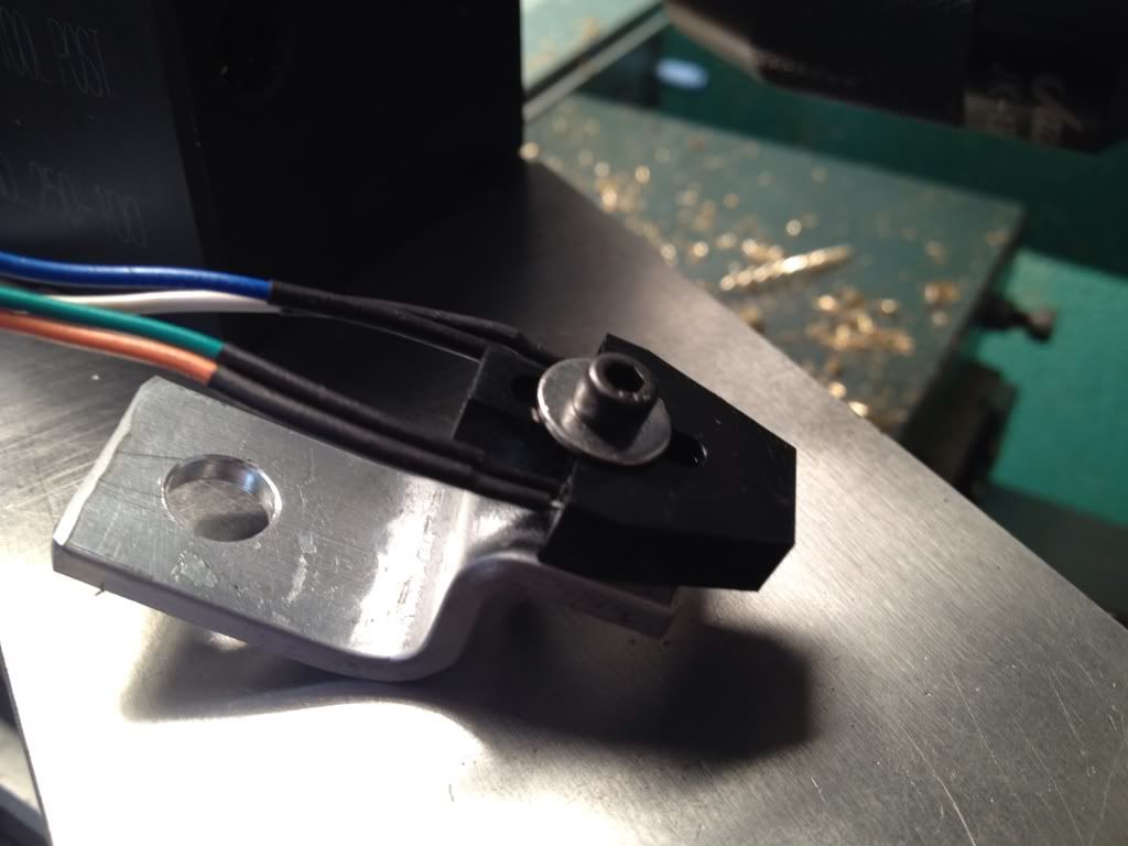


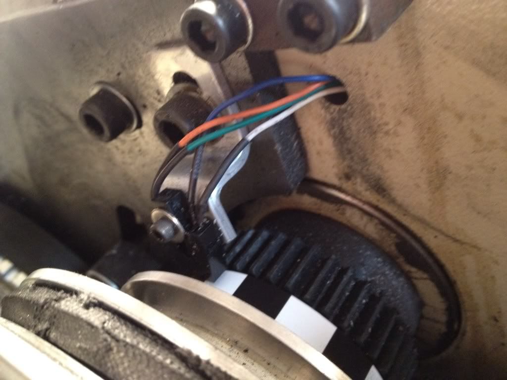
The sensor mounted with a 16 segment timing strip on the pulley. You can actually use any number of segments from 1 to 16. The low end accuracy increases with the number of segments. 16 is the max and, according to the specs, is accurate to 3 rpm. The very strange thing was the first timing strips I made were printed on a pigment ink, inkjet printer. (Epson 9800). The IR sensor refused to recognize the difference between black and white. The instructions mention this issue with some laser printers and suggest switching to a laser printed sensor strip. I did so and it works perfectly. Go figure. Must be an issue with reflectivity of pigment inks. Inexpensive ink jets that use dye inks apparently don't have this issue.


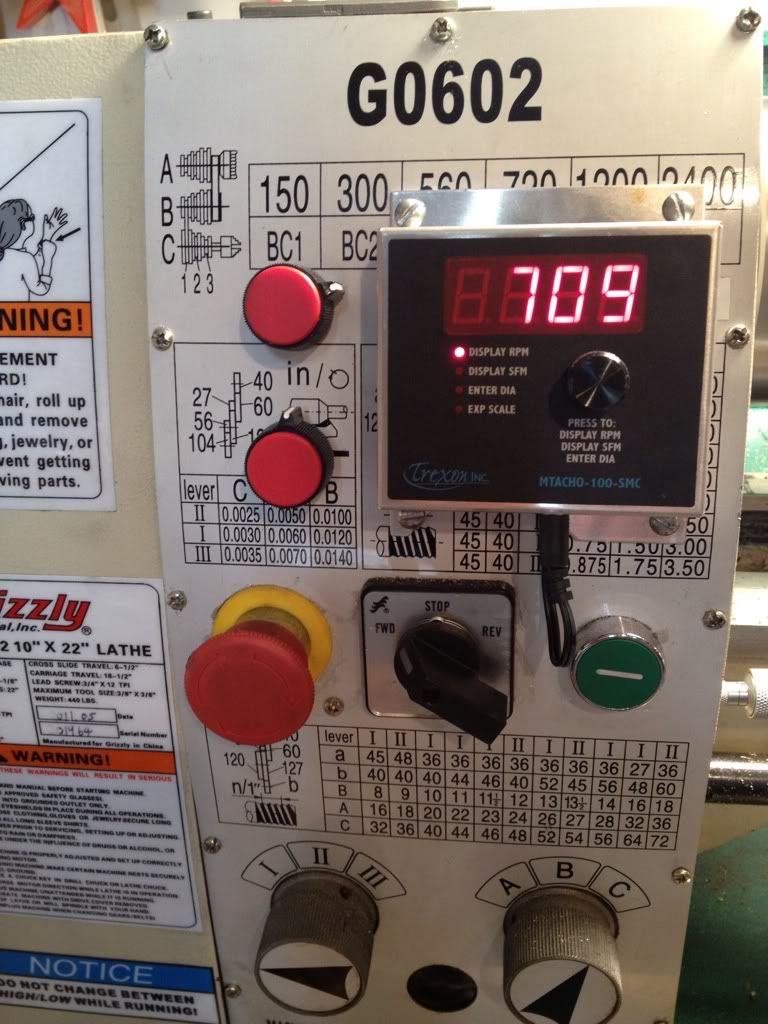
FInished with the control box mounted on the lathe. The two knobs to the left (labeling is coming) are the speed pot for the Teco FM50 VFD and, below it, the speed control for the carriage feed.


Happy to answer any questions.

Best,
Stan
Best,
Stan

Offline Noitoen

  • Full Member
  • ***
  • Posts: 143
  • Country: pt
Re: Tach install
« Reply #1 on: August 09, 2012, 03:15:23 PM »
Tachulator Tachometer with calculator  :beer: Nice build.
On some VFD's you can program a dividing factor to display an RPM Value based on the frequency. If you have just one pulley ratio, you can display the spindle's RPM's.

Offline BillTodd

  • Hero Member
  • *****
  • Posts: 1099
  • Country: 00
  • Colchester Essex (where the lathes were made)
Re: Tach install
« Reply #2 on: August 09, 2012, 04:32:51 PM »
Tachulator Tachometer with calculator  :beer: Nice build.

THe SFM calculator sound useful :)

Quote
On some VFD's you can program a dividing factor to display an RPM Value based on the frequency. If you have just one pulley ratio, you can display the spindle's RPM's.

I've just got working on my Haighton mill using a ABB vfd.  The VFD has a frequency input (via one of the I/O ports) so I feed it with an input from a sindle sensor and programmed the VFD to display actual  spindle RPM .

Now, I'll have to look in to a SFM function :)

Bill

Offline WillieL

  • Full Member
  • ***
  • Posts: 108
  • Country: us
  • This space for rent.
Re: Tach install
« Reply #3 on: August 18, 2012, 12:23:25 AM »
Great job Stan.   :thumbup:

Another vote for the "tachulator"....   :beer:
http://madmodder.net/index.php/topic,6766.0.html
WillieL

Midwestern USA

Offline John Stevenson

  • In Memoriam
  • Hero Member
  • *****
  • Posts: 1643
  • Nottingham, England.
Re: Tach install
« Reply #4 on: August 18, 2012, 03:36:34 AM »
I gather you don't do any metric screw cutting ?
John Stevenson

Offline sshire

  • Jr. Member
  • **
  • Posts: 26
  • Country: us
    • LS Editions
Re: Tach install
« Reply #5 on: August 18, 2012, 09:18:35 AM »
John
I do as little screw cutting as possible. Changing gears is an activity that I avoid. I've tried it a few times early on with completely disastrous results.  I envy those with quick change gearboxes and have most (if not all) of the imperial screw sizes that I need for my engines. After a year of machining I've acquired many skills: turning to a precise diameter, boring, etc. most of the metric threads that I absolutely must use (to mount the DRO on my lathe and mill in already existing holes) have been M6 and I bought a box of them to be cut to length. I generally use a die in a holder on the lathe tailstock to cut threads.
That said, when I finish the Epicyclic Engine that is the current project, I intend to master single point threading on the lathe.
Best
Stan
Best,
Stan

Offline WillieL

  • Full Member
  • ***
  • Posts: 108
  • Country: us
  • This space for rent.
Re: Tach install
« Reply #6 on: August 18, 2012, 09:26:06 AM »
I like to keep the motor frequency near rated levels whenever possible, no matter what the spindle speed is.
I'm not a big fan of over-clocking or under-clocking the motor speed and using a single gearbox speed.
But that's just me.

I don't have an inverter duty motor.  :coffee:
WillieL

Midwestern USA

Offline Noitoen

  • Full Member
  • ***
  • Posts: 143
  • Country: pt
Re: Tach install
« Reply #7 on: August 20, 2012, 02:50:54 PM »
If you set a parametrize an inverter correctly, there is no problem with running a motor at any frequency. Inverter duty motors are important for 400v motors mainly because of the high voltage spikes (over 550v) delivered by the inverter to the motor. On 230v motors this doesn't present any problems.  Also if you are going to run a motor at a continuous low speed, the motor's fan won't have the efficiency to self cool, nothing a little external fan can't solve. If you're going to "over-clock" the motor, since the motor has a linear voltage/frequency curve, when you exceed the rated frequency, you should also exceed the voltage on the same proportion and the only way to do this is to run a 110v 3~ motor on 220v inverter or a 220v 3~ motor on a 400v inverter. By letting the inverter know this, it will drive the up to 87Hz for a 50Hz motor, increasing  the motor's power 174%.