Author Topic: Mill Electrotrickery Part 1 - Stepping out with Arduino  (Read 22799 times)

Offline RodW

  • Full Member
  • ***
  • Posts: 120
  • Country: au
    • Vehicle Modifications Network
Mill Electrotrickery Part 1 - Stepping out with Arduino
« on: May 11, 2013, 08:21:03 AM »
Well you guys told me to get my act together and share some projects. I have two on the go at the moment but. One is a power feed for my Seig SX3 mill based on a 14.4 volt cordless drill motor and the other is adding an Arduino controlled electronic dividing controller for my as yet unused Vertex Rotary table. I think they will be firly slow builds as I still work and getting quality shed time is pretty hard!

But anyway here is part 1  of part 1....

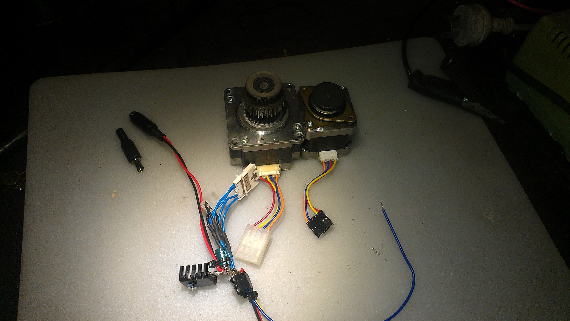
I have some stepper motors in a box of tricks. three of them are NEMA17 and 1 of them is a NEMA 23. I have seen a few people use an Arduino to make a rotary table NC controller and because I have played with these beasts, I thought I would give it a go. So being in Australia, I grabbed one of these


http://littlebirdelectronics.com/products/arduino-uno-r3
and one of these


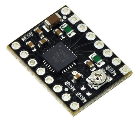
http://littlebirdelectronics.com/products/a4988-stepper-motor-driver-carrier-black-edition

and I figured I better be able to see what is going on, so I got one of these


http://littlebirdelectronics.com/products/lcd-keypad-shield-1

and a tiny heatsink

http://littlebirdelectronics.com/products/small-heatsink

And in exactly the same time it took to get an order from CTC from Hong Kong, it all arrived from Sydney 800 km away. Lucky I paid extra for Express Post  :thumbup:

Anyway, I busied myself with configuring the Arduino and remembering how to code in C but by the end of the night, I had got some code written that very roughly used the keyboard. The video thumbnail gives you an idea how big the stepper controller is.


Anyway, not too bad for one night. The next night, I headed for the shed, grabbed my soldering iron and started to put some stuff together


So what have we got?

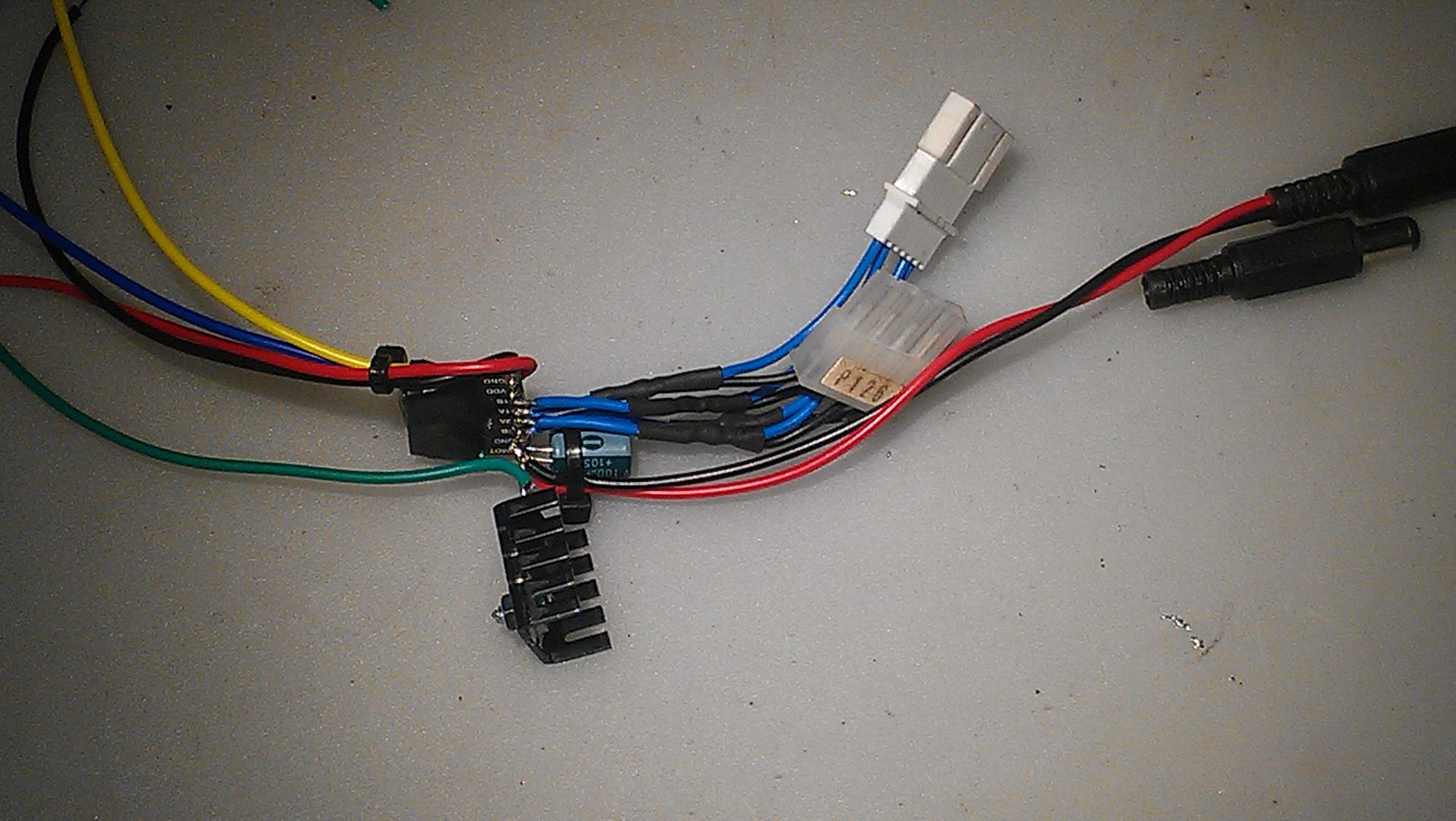
Well I started off soldering on two different sized stepper drive connectors. One for NEMA23 and one for NEMA 17. To the right is an inline power connector to receive 18.5 volts from a laptop power supply once I solder on the loose connector beside it. At the bottom is a 12 volt regulator and heatsink to step the 18.5 volts down to power the Arduino. Above that is the stepper board itself wrapped in insulation tape holding the heatsink on while the heatsink plaster/glue dried. The red and black wires will feed the logic side of the stepper board from the built in 5 volt regulated power on the Arduino. The blue and yellow wires are the step and direction signals and the green wire is 12 volt power for the main Arduino supply.

Here's another pic


So it s night three and time to see if I can get the stepper going. Initially I had trouble and I found a bit of code on the Pololu forum that did the trick but not straight away as it was a bit hit and miss. I wondered if the tinned wires I had stuffed into the Arduino ports were not getting a good connection so back to the shed to solder them onto a header strip and this time, it worked perfectly!


So now if you are hooked on this project, here are a few more short videos (all of these are taken with my phone). I tried to merge them together but it took ages. There is only 7 minutes video in total so enjoy


This one shows an overview of the bits

This one talks about the keyboard.


SO I had a bit of a play with this all for the evening and concluded the NEMA 17 was a better match with the controller but that I was really asking too much of the postage sized stepper controller and was thinking I might get a Gecko GX251X controller.

http://www.geckodrive.com/geckodrive-step-motor-drives/g251x.html

Unfortunately, I don't have any specs on these steppers. I think they must be custom made by Minebea. I think the bigger one is 3.3 amps and the smaller ones must be around 1 to 1.4 amps based on specs of available products from the manufacturer.

Anyway, I will just focus on developing the software in the evenings now I know I have a goer and finish off as few part finished jobs.

For the programmers, here is the short sketch I found that is driving stuff in the second video.

Code: [Select]
#define stepPin 4
#define dirPin 5
int dir = HIGH;

void setup() {
  Serial.begin(9600);
  Serial.println("Starting stepper exerciser.");

  pinMode(stepPin, OUTPUT);
  pinMode(dirPin, OUTPUT);

  digitalWrite(dirPin, HIGH);
  digitalWrite(stepPin, LOW);
}

void loop() {
  int i, j;

//  for (i=2000; i>=400; i-=200) {
//    Serial.print("Speed: ");
//    Serial.println(i);
   
    i = 400;    // maximum speed it can do
    for (j=0; j<1000; j++) {
      digitalWrite(stepPin, HIGH);
      delayMicroseconds(i);
      digitalWrite(stepPin, LOW);
      delayMicroseconds(i);
    }

    delay(500);
    digitalWrite(dirPin, !digitalRead(dirPin));

    for (j=0; j<2000; j++) {
      digitalWrite(stepPin, HIGH);
      delayMicroseconds(i);
      digitalWrite(stepPin, LOW);
      delayMicroseconds(i);
    }

    delay(1000);
    Serial.println("Switching directions.");
    if(dir == HIGH)
      dir = LOW;
    else
      dir = HIGH;
    digitalWrite(dirPin, dir);
//  }
}

Pretty simple Huh!

So here's where I can use some help so feel free to chip in to answer some questions.

1. Which sized stepper should I use on  a Vertex Rotary Table? NEMA 17 or NEMA 23?
2. What features should a stand alone Rotary Table controller support?
3. Which "Real" stepper driver should I get?
4. Can you live with a slow build?
RodW
Brisbane, Australia

Offline Swarfing

  • Sr. Member
  • ****
  • Posts: 417
  • Country: gb
Re: Mill Electrotrickery Part 1 - Stepping out with Arduino
« Reply #1 on: May 11, 2013, 08:51:14 AM »
I would go with the stepper that has the greatest holding torque. As for the driver, cant see you would need one above a couple of amps. Match the driver to the stepper?
Once in hole stop digging.

Offline raynerd

  • Madmodder Committee
  • Hero Member
  • *****
  • Posts: 2893
  • Country: gb
    • Raynerds Projects - Raynerd.co.uk
Re: Mill Electrotrickery Part 1 - Stepping out with Arduino
« Reply #2 on: May 11, 2013, 05:00:43 PM »
Quote
2. What features should a stand alone Rotary Table controller support?

Take a look at Steves CNC rotary table. I have built 3 now and wouldn't be without them.

http://www.worldofward.com/rotarycontroller/overview/

I use most of the features and now I've set up one on my x axis on my milling machine, I use the programme mode, link it to the CNC rotary table!

Good luck! I think someone on here has definitely been making or even made an arduino based rotary divider already.

Chris
« Last Edit: May 12, 2013, 02:19:03 AM by raynerd »

Offline RodW

  • Full Member
  • ***
  • Posts: 120
  • Country: au
    • Vehicle Modifications Network
Re: Mill Electrotrickery Part 1 - Stepping out with Arduino
« Reply #3 on: May 11, 2013, 11:57:00 PM »
Thanks for the ideas, keep them coming.

Raynerd, thanks for the link, I had not read about that one. It looks very well featured. I had thought about some sort of programable capability it it looks like someone beat me to it.

I just wish I had more time. By the time I turned up the parts I had to make, clean up my shed a bit and finally get my 4 jaw chuck jaws closing  smoothly, the day was half gone. The chuck is something I have been putting off since I bought the lathe in January. I had one go at it back then and I was putting it off because it was a boring job.
RodW
Brisbane, Australia

Offline RodW

  • Full Member
  • ***
  • Posts: 120
  • Country: au
    • Vehicle Modifications Network
Re: Mill Electrotrickery Part 1 - Stepping out with Arduino
« Reply #4 on: May 13, 2013, 10:50:12 AM »
I ordered a Gecko g251 stepper motor drive controller today. For some reason they are cheaper in Australia than the US! Anyway, at 3.5 amps, I,am sure it will fix some problems on the interface front.

I also ordered a couple of misalignment couplers from eBay.

 The software is slow going. I want to get the low level keyboard routines right and my first approach has some flaws but I am sure it will come together if I sleep on it. I would rather get the input and menu systems right before moving onto just cobbling something together as it will be easier in the long run.

I also ordered a variable speed motor controller from eBay for my part 2 project, the mill power feed.
RodW
Brisbane, Australia

Offline RodW

  • Full Member
  • ***
  • Posts: 120
  • Country: au
    • Vehicle Modifications Network
Re: Mill Electrotrickery Part 1 - Stepping out with Arduino
« Reply #5 on: May 14, 2013, 12:32:06 AM »
I have worked out what the menu structure should look like for this project and decided to order an SD card reader for the Arduino. It cost all of $13.00

If I can get it to play nicely with the display, it will allow programs to be created in a text editor on a computer and read from the SD card by the Arduino. I may also deal with device profiles too.

If it works out, the SD card will substantially simplify the coding required to support the more advanced features proposed.

I'll work on the menus and input routines while waiting for the hardware to arrive.
RodW
Brisbane, Australia

Offline RodW

  • Full Member
  • ***
  • Posts: 120
  • Country: au
    • Vehicle Modifications Network
Re: Mill Electrotrickery Part 1 - Stepping out with Arduino
« Reply #6 on: May 16, 2013, 04:35:44 PM »
Well the SD card arrived last night but I have not played with it yet. I have been working on some code for menus and string entry. I have been doing this on a PC using Visual Studio so it will need to be reworked slightly for the Arduino string display. So I have a reworking menu dispatcher now as well a procedure to get a number and select a string from a list. To enter a number you use left and right arrows to select different digits (skipping any decimal point) and the up and down arrows increment or decrement the digit. The string selector works by using the left and right arrows to move up and down the list of strings supplied and refreshes the display. I will add an alpha numeric string data entry routine and then I think the next step will be to work on displaying multiple data entry field on a single screen and navigating between.

I will say it has been years since I have done much in C and I have found I have forgotten so much so it has been taking a long time to relearn how to code what I envisioned. I have spent hours tinkering with stucture definitions until I finally got stuff compiling without errors or warnings!  :bang:
RodW
Brisbane, Australia

Offline RodW

  • Full Member
  • ***
  • Posts: 120
  • Country: au
    • Vehicle Modifications Network
Re: Mill Electrotrickery Part 1 - Stepping out with Arduino
« Reply #7 on: May 19, 2013, 06:52:07 AM »
I soldered the SD card controller board onto a Protyping shield andmanaged to get the demo programs compiling. I have given the SD card a bit of a workout and it is all good. There is a trick using the SDfat library. I followed the pinouts on the SD card web site and put Chip select on Pin 4 but SDFat wanted it on pin 10. Once I sorted this out, it was pretty easy to read and write t the card and I even formatted it!. Nothing much to look at, but here is the protoshield I soldered up  with the SD card good to go.


This is the SD card that  bought but m still waiting for the stepper drive board to arrive
http://www.dfrobot.com/index.php?route=product/product&filter_name=sd%20card&product_id=875#.UZivFbVmh8E

RodW
Brisbane, Australia

Offline RodW

  • Full Member
  • ***
  • Posts: 120
  • Country: au
    • Vehicle Modifications Network
Re: Mill Electrotrickery Part 1 - Stepping out with Arduino
« Reply #8 on: May 24, 2013, 07:59:26 AM »
Well, I have finally got some working menus to show off. You would not believe how many hours have gone into programming to get this far.

First, I had to remember a fair bit about C, then I had to develop a class to manage the keyboard and then integrate that with a buggy Menu system that mostly does what I want.

I have also got an SD card sandwiched between the screen and the Arduino which will explain why some of the menus exist.


Note at the end of the video, where I am talking about a motor controller, it will go on my mill power feed, not on the Rotary table.

The program started to behave erratically before I had finished building the menus which is a sure sign I had run out of RAM. On closer investigation, the third party Menu library was creating duplicate strings of all of the menu options so we were using twice as much RAM as we needed to. Given the Arduino only has 2k of RAM space for storing variables, this was a serious problem. I might add that had the menu developer bothered to use any error checking which could have easily alerted me of the memory overflow. Anyway, I moved all of the menu descriptions to a static string array and this saved the day. This also let me reuse strings which trimmed the memory usage down quite  a bit and the code is a few K slimmer now.

Anyway, hopefully it won't take long to develop the field input routines and screen navigation stuff and I can start coding the stuff that really matters.

But at this point the backbone of the program exists as each menu option is calling a stub procedure so once I get going, all I have to do is progressively work my way through the code that talks to the attached hardware.
RodW
Brisbane, Australia

Offline kwackers

  • Sr. Member
  • ****
  • Posts: 356
Re: Mill Electrotrickery Part 1 - Stepping out with Arduino
« Reply #9 on: May 28, 2013, 04:14:15 AM »
Not sure if you realise this but if you don't declare your strings 'const' then they'll sit in ROM and be copied to RAM when the your program starts.
The reason for this is that a string that isn't declared const is presumed to be modifiable and thus would need copying...

I don't play with arduino's that much so haven't seen the menu system you speak of but I'd expect the functions to take const string pointers.

I'd be inclined to write my own menu's. Most 'systems' are over complex for the sort of stuff you need on LCD's and can invoke a fair bit of overhead.
In the code for the rotary table Chris linked to above there are just two functions.
The first is an init routine which simply prints the new screen.
The second is the handler which reads the keyboard and executes a switch statement to call the appropriate function(s).

Due to the lack of stack depth the menu system is non-hierarchical and simply consists of a variable with the current state which each loop through the main code simply 'switches' to the correct menu handler. Changing menus is then a simple task of calling init with the new state, this calls the appropriate print routine to draw the new screen and sets the new menu state. Subsequent loops through main will then call the appropriate handler.

It's slightly more hard wired than a 'system' could be but imo it's quicker and easier to knock stuff up with, particularly if you need to leave the beaten track. I did originally consider writing a more complex system that could automate various animation and data entry fields but I felt they'd exist just to show how clever the system was rather than making things easier.

Offline RodW

  • Full Member
  • ***
  • Posts: 120
  • Country: au
    • Vehicle Modifications Network
Re: Mill Electrotrickery Part 1 - Stepping out with Arduino
« Reply #10 on: May 28, 2013, 05:52:15 AM »
Kwackers, thanks for the feedback, much appreciated. I know you have a controller out there, did Chris link to yours?

I used to know C backwards and once managed to squeeze a compete inventory system into a 64k hand held terminal but that was 30 years ago. However I am very rusty with the language and the Arduino which I played with a few years ago. The thing I am really struggling to remember is the advanced type definitions and defining more complex data structures.

I started to write my own menu systems and got it going but when I found this library, it was written much the way I wanted mine to end up so I decided to run with it to save some time. Of course, this immediately exposed me to someone else's poor practices which included not using constant Flash memory for menu items and not checking for errors when allocating memory, both of which bit me. Some of the other libraries I looked at were useless! I managed to halve his memory usage but had problems accessing Flash memory variables so moved on to other tasks while I learn the Flash memory ropes.

Now I have a problem to solve with an Arduino that requires a screen and keyboard, I wanted to write a robust modules for menus, field input and processing a screen and navigate around multiple fields for future projects.

The Arduino has a F() macro and the PROGMEM variable modifier to deal with strings stored in Flash memory and I have nearly got my head around this. Well enough to store my own code there anyway!

Anyway, moving right along, this is my evening project as I have other more critical projects competing for shop time. I have just about got the field input stuff working the way I want it and using Flash memory for field prompts, but need to wrap it into an Arduino Library and then build the screen handling. Once this is done, I will be ready to actually start dividing!

I think, at this stage, there is heaps of Memory with the Arduino to do what I want to achieve. 32k Flash memory, 2k volatile memory and 1k of EEPROM. I thought I would see if I could incorporate the SD card to reduce the overhead of any scripting features etc I may add as they can be written in a text editor but time will tell how much I can squeeze in!


RodW
Brisbane, Australia

Offline kwackers

  • Sr. Member
  • ****
  • Posts: 356
Re: Mill Electrotrickery Part 1 - Stepping out with Arduino
« Reply #11 on: May 28, 2013, 10:38:15 AM »
No probs,
yeah the link Chris posted was to mine. Like you I wrote something out of interest that would do a particular job for me. Once it was finished I made it more commercial and published the design. Haven't done much work to it for a few years now but then apart from making it into something else there isn't really anything more I can do.

I started out by writing computer games on small platforms so I'm fairly used to squeezing lots of code and data into small spaces (although for many years that was done by coding it all in assembler).
For these sorts of projects a typical Arduino / PIC is massively well endowed! If I was doing something now I'd be tempted to make it wireless and give it a web page you could access on your local network just for the hell of it...  :loco:

Interesting stuff.

Offline RodW

  • Full Member
  • ***
  • Posts: 120
  • Country: au
    • Vehicle Modifications Network
Re: Mill Electrotrickery Part 1 - Stepping out with Arduino
« Reply #12 on: May 28, 2013, 04:00:32 PM »

For these sorts of projects a typical Arduino / PIC is massively well endowed! If I was doing something now I'd be tempted to make it wireless and give it a web page you could access on your local network just for the hell of it...  :loco:

Interesting stuff.

Don't give me ideas now. My home network has its own web site and the exterior Wireless Access Point covers the shed.... The enhancement I had thought of was incorporating a rotary encoder knob which might simplify data input and could allow you to rotate the table. By then I think I might almost have run out of ports so maybe the internet connected table might not get off the ground... But I agree,  it would be cool to be able to push a new config to it via the web.
RodW
Brisbane, Australia

Offline raynerd

  • Madmodder Committee
  • Hero Member
  • *****
  • Posts: 2893
  • Country: gb
    • Raynerds Projects - Raynerd.co.uk
Re: Mill Electrotrickery Part 1 - Stepping out with Arduino
« Reply #13 on: May 29, 2013, 01:44:28 PM »
If I was doing something now I'd be tempted to make it wireless and give it a web page you could access on your local network just for the hell of it...  :loco:

Interesting stuff.

I presume this will be in the 2013 code  :)  :whip:

A few years ago, you may remember, kwackers, that I wrote an x axis controller. It was pants (I'm sure you imagine since I made it  :Doh: ) but did the job. However, I've now moved over to using another of your controllers for linear travel of my x axis! It would be fab if there was a linear mode built into it, I'm guessing it would work identically just at the moment I have to set it so that x degree (can't remember off hand) equates to 10mm. Due to the steps per revolution figure maximum value, I can't get 1 deg to equal 1mm .

Something you may wish to design on your arduino controller as well rod?

Chris

Offline RodW

  • Full Member
  • ***
  • Posts: 120
  • Country: au
    • Vehicle Modifications Network
Re: Mill Electrotrickery Part 1 - Stepping out with Arduino
« Reply #14 on: May 29, 2013, 04:39:40 PM »
Quote from: raynerd
I presume this will be in the 2013 code  :)  :whip:

A few years ago, you may remember, kwackers, that I wrote an x axis controller. It was pants (I'm sure you imagine since I made it  :Doh: ) but did the job. However, I've now moved over to using another of your controllers for linear travel of my x axis! It would be fab if there was a linear mode built into it, I'm guessing it would work identically just at the moment I have to set it so that x degree (can't remember off hand) equates to 10mm. Due to the steps per revolution figure maximum value, I can't get 1 deg to equal 1mm .

Something you may wish to design on your arduino controller as well rod?

Chris

Chris, is am being dragged kicking and screaming from old K&R C to the advanced constructs of C++ which has a lot of advantages so I will do my best.

Its funny you mention this. I know a software developer who is into woodwork and he wanted to turn a leadscrew to move the backstop on his table saw so 300mm = 300mm so I have given this matter some thought.

I think the issue is the drive is much more direct as you are missing the 90 turns to the revolution  gearing of the rotary table. Some stepper controllers do micro stepping, the $10 Polou driver i first played with has the option to go down to 1/16 of a step movement per step by setting some additional signals on the board. The gecko controller I have purchased but not quite ready to play with (been a busy week) has a stated resolution of 10 micro steps hard wired in. So for the 200 step per rev steppers like mine that means you have 2000 steps per revolution. So if you have a 2mm pitch leadscrew If I get the maths right, you would have 1000 steps per mm (0.0001 mm per step). So perhaps the lack of resolution you are experiencing can be simply resolved with a stepper driver board upgrade or by setting a few signals to increase the resolution of your existing controller. It is 2013 after all!
RodW
Brisbane, Australia

Offline John Stevenson

  • In Memoriam
  • Hero Member
  • *****
  • Posts: 1643
  • Nottingham, England.
Re: Mill Electrotrickery Part 1 - Stepping out with Arduino
« Reply #15 on: May 29, 2013, 05:05:18 PM »
Sorry Rod, microstepping doesn't work like this.

Does in theory but as soon as you loose a signal it looses position and the motor jumps to the nearest step magnetically.

Or something along these lines.
John Stevenson

Offline RodW

  • Full Member
  • ***
  • Posts: 120
  • Country: au
    • Vehicle Modifications Network
Re: Mill Electrotrickery Part 1 - Stepping out with Arduino
« Reply #16 on: May 29, 2013, 05:12:52 PM »
Sorry Rod, microstepping doesn't work like this.

Does in theory but as soon as you loose a signal it looses position and the motor jumps to the nearest step magnetically.

Or something along these lines.

I think you have explained why a commercial product I saw has a Hall effect sensor added to the rotary table to set the home position.  More food for thought! You can also get 1024 step rotary position shaft sensors for about $45 from Sparkfun which could sense this movement if it had power :)
RodW
Brisbane, Australia

Offline kwackers

  • Sr. Member
  • ****
  • Posts: 356
Re: Mill Electrotrickery Part 1 - Stepping out with Arduino
« Reply #17 on: May 30, 2013, 04:01:05 AM »
The main reason microstepping exists is to drive the motors smoothly by effectively generating out of phase sine waves (think 3 phase motor - but with only two phases...)
If you try to use the microstepping to give you resolution you'll be disappointed, along with losing position as John mentions the reality is that the positional accuracy of the micro steps is poor and it also varies depending on load. Full or half steps however pretty much lock mechanically to a fixed position so are fairly accurate and less load dependent.

With regards linear positioning, I've had a few goes at it but always get beaten by feature creep... I start with a simple power feed and before you know it I'm planning ahead for a whole range of stuff from tapers to screwcutting to profiles (along with the necessary two axis drive). At this point I always figure that Mach 3 can do this sort of thing better and computers are cheap...


Offline RodW

  • Full Member
  • ***
  • Posts: 120
  • Country: au
    • Vehicle Modifications Network
Re: Mill Electrotrickery Part 1 - Stepping out with Arduino
« Reply #18 on: May 30, 2013, 08:33:11 AM »
Thanks for all of the help guys. I can see I need to run up the new stepper controller I have. It does not appear to have a way to turn off microstepping from the specs.

I am coming at this from a zero base so have a lot to take in so your help is appreciated.

Spent the evening trying code something and finally discovered that my old favourite sprintf() does not support  "%f" in format strings and I have to use dtostrf() instead. Then found that "value" is perfectly OK to use as a variable name but p->value generates an error in dtostrf! Don't you love programming!  :doh:

Anyway, I have a clearer idea of data structures I will need. I want to create a NULL terminated linked list of fields that are displayed on one screen so you can navigate between them. I have had a couple of very busy days so have not felt like doing much in the evenings but at least some progress is happening.

RodW
Brisbane, Australia

Offline raynerd

  • Madmodder Committee
  • Hero Member
  • *****
  • Posts: 2893
  • Country: gb
    • Raynerds Projects - Raynerd.co.uk
Re: Mill Electrotrickery Part 1 - Stepping out with Arduino
« Reply #19 on: May 30, 2013, 02:50:17 PM »
The main reason microstepping exists is to drive the motors smoothly by effectively generating out of phase sine waves (think 3 phase motor - but with only two phases...)
If you try to use the microstepping to give you resolution you'll be disappointed, along with losing position as John mentions the reality is that the positional accuracy of the micro steps is poor and it also varies depending on load. Full or half steps however pretty much lock mechanically to a fixed position so are fairly accurate and less load dependent.

With regards linear positioning, I've had a few goes at it but always get beaten by feature creep... I start with a simple power feed and before you know it I'm planning ahead for a whole range of stuff from tapers to screwcutting to profiles (along with the necessary two axis drive). At this point I always figure that Mach 3 can do this sort of thing better and computers are cheap...

True, comps are cheap but Mach3 isn't and I find it more convenient to have a dedicated controller unit in a small box than a PC and monitor! I am sure people would be well interested if you released something like this without 101 features. I'd love to see some mikroC code!!

;-)

Chris

Offline RodW

  • Full Member
  • ***
  • Posts: 120
  • Country: au
    • Vehicle Modifications Network
Re: Mill Electrotrickery Part 1 - Stepping out with Arduino
« Reply #20 on: May 30, 2013, 04:33:44 PM »
There are plenty of examples of Arduino CNC. There is a G-Code interpreter available for it (open source) and there are some custom boards for 3D printers if you want a small CNC controller with the stepper drivers built in on eBy for about $130. I am not that keen on converting any of my stuff to CNC but would like some push button convenience on the rotary table and maybe a power lifter to wind the Z axis up and down as the Seig is pretty manual to adjust. I reall have enough to learn about this hobby without learning how to drive 3d design software.

As Kwackers says, the biggest problem is scope creep once you start thinking about interfacing CPU's with the outside world!
RodW
Brisbane, Australia

Offline RodW

  • Full Member
  • ***
  • Posts: 120
  • Country: au
    • Vehicle Modifications Network
Re: Mill Electrotrickery Part 1 - Stepping out with Arduino
« Reply #21 on: May 31, 2013, 12:29:58 AM »
Well, I have finally sorted out how the field navigation will work but still have not much to show for it yet. I have coded different procedures for different field types (with a few more to go but they are just variants of what is already done).

So each field has a structure that defines where it lives on the screen and data it needs. For a number it looks something like this:
Code: [Select]
typedef struct  getnumstr_t
{
int x;                       // X ordinate
int y;                       // Y ordinate
        char width;                  // Field width
        char prec;                   // Field Precision
        const char PROGMEM *prompt;  // prompt
        double  *num;                // Number 
}; // Field that enters a string value

This is not quite how I wanted it to be but the Arduino does not support sprintf() for doubles and floats and you have to use the AVR function dtostrf() instead hence the values for width and precision.

For a list of string options (think choose from a list like "Clockwise" or "Anticlockwise"), it looks like this:

Code: [Select]
typedef struct getoptionstr_t
{
int x;                        // X ordinate
int y;                        // Y ordinate
        const char PROGMEM *prompt;   // Prompt
char **values;                // NULL terminated array of values to display to choose from
}; // Field that scrolls though a list of values

Then these field types have their own function to enter the data
Code: [Select]
char *getnum(getnumstr_t *p);
char *getstr(getstr_t *p);
char *getoptstr(getoptionstr_t *p);

And the screen will be made up of a linked list of these fields held in a structure like this

Code: [Select]
typedef struct screenfield_t
{
        void *userdata;        // Pointer to field structure
        char fieldType;        // Field Type for UserData
        screenfield_t *prev;   // Previous field, NULL for first
        screenfield_t *next;   // Next field, NULL for last
}; // Screen Field type definition

So to process several fields shown on the display at one time, it will look like this

Code: [Select]
screenfield_t *despatchfield(screenfield_t *p, char fieldtype)
{
   char *c; 
   switch(p->fieldType){
       case FIELD_OPTION:
                 c = getoptstr((getoptionstr_t *) p->userdata);
                 break;
       case FIELD_STRING:
                 c = getstr((getstr_t *) p->userdata);
                 break;     
       case FIELD_NUMBER:
                 c = getnum((getnumstr_t *) p->userdata);
                 break;                   
       default:
             return NULL;
   }
  if(!c)
    return(p->prev;
  else
    return p->next; 
}

The list of field types might shrink before I am done but presently, I though they would be

Code: [Select]
// These define the type of field a given screenfield_t UserData pointer is pointing to
#define FIELD_NONE    0    // No Field
#define FIELD_OPTION  1    // Select from a list of text based options
#define FIELD_STRING  2    // String field
#define FIELD_NUMBER  3    // Number Field
#define FIELD_DEGREE  4    // Degree Field, decimal, Maxiumum = 359.999
#define FIELD_DMS     5    // Degrees, Minutes, Seconds, Maximum =  359°59"59'
#define FIELD_ANYKEY  6    // Press any Key
#define FIELD_YESNO   7    // Yes or No?
#define FIELD_BOOL    8    // True or False?

There was some fairly heavy thinking in this which I had been avoiding for a while so I am pleased that I now have  a plan of attack. I still have to do field types 4-8 but 7 and 8 are simply calls to field type 1.  4 and 5 are variants of  field type 3 so the heavy lifting is done...

Defining a numeric field looks something like this:

Code: [Select]
     char  FNumStr[] PROGMEM = { "Number:" } ;             // Store the Prompt in Flash memory with the program code
     double fnum  = 121.23;                                // Define a variable to edit
     getnumstr_t num = {0 , 0, 7, 2, FNumStr, &fnum,};     // define the field data structure

I think the code should be pretty compact. I debated whether to work with floats and doubles but decided that I could put up with the extra memory usage as working solely in integers would just get confusing and lead to some convoluted code. I figured once we get into dividing we will want to use fractions in the maths somewhere!

Give me another week and I might have some data entry stuff to show of for my efforts and finally I might start playing with stepper hardware again.
RodW
Brisbane, Australia

Offline kwackers

  • Sr. Member
  • ****
  • Posts: 356
Re: Mill Electrotrickery Part 1 - Stepping out with Arduino
« Reply #22 on: May 31, 2013, 03:46:12 AM »
If you're using floats be careful of accumulating rounding errors.

I went with ints for mine but that was because I wanted the motor drive to occur inside an interrupt which means I can do other non time-dependent things in the mainloop (like updating the display and scanning the keyboard etc). To run inside interrupts at the sorts of rates that are realistically required meant efficient int code was needed. (For a 40mhz PIC18 at any rate).

I have some code for a six axis driver I wrote for a high end PIC (or arduino). Again I had to go with ints to get all six axis to drive at a decent speed (50khz I think was my target) and again using interrupts.
The G code interpreter I started writing for it was float based though, this ran in the main loop and kept a buffered list of data for the motor driver to consume.
I never got as far as writing the IO system for this because I was going to go with a graphical display (to see toolpaths etc) but the low end graphic displays I checked out were just too slow imo to be useful and the decent stuff cost as much as a low end PC!

Offline RodW

  • Full Member
  • ***
  • Posts: 120
  • Country: au
    • Vehicle Modifications Network
Re: Mill Electrotrickery Part 1 - Stepping out with Arduino
« Reply #23 on: May 31, 2013, 06:44:04 AM »
Thanks Kwackers, I am onto the problems around data types. I started off just dealing with inputting an numeric string and convert it on return to deal with this but then decided to pass numeric values. My original plan was to use a picture field for data entry as found in some higher end programming languages and look for a decimal point to decide if it was an int or a float. Then I decided the picture might as well be a format string for printf() but because the AVR does not support %f in format strings by default I had to scratch the idea. I can still do this based on the precision parameter required for the dtostrf() to do the same. Eg. If prec == 0, do some fancy footwork with pointers and return an int by reference otherwise return a float. For the input routines I then thought I could get away with casting values back to an int once the value was read. I will wait and see how it pans out.

As far as interrupts go, I have one available as the screen shield stole one of the interrupt ports  and the platform lets you to hook onto the timer interrupt which sounds more useful for this project. I have been careful not to write any blocking code ( eg, no calls to delay()).

I did do some tests with the stepper measuring the number of nanoseconds required to change the port state and measure the processing overhead and it was pretty amazing. I can't quite remember but it was something like 23 nanoseconds from memory but don't quote me until I fire up a PC instead of my iPad to look it up.

Anyway, I appreciate your input as it makes me think. While I was writing this, I realised that I could return either a long or a float by reference as they are both 4 bytes long! That might be pretty cool to enter both longs and floats with the same procedure! Casting a long back to an int would be much safer way to go.
RodW
Brisbane, Australia

Offline Noitoen

  • Full Member
  • ***
  • Posts: 143
  • Country: pt
Re: Mill Electrotrickery Part 1 - Stepping out with Arduino
« Reply #24 on: June 09, 2013, 12:57:57 PM »
I was going to re invent the wheel by designing a dividing controller with a PIC18F452 micro controller and then I found this: http://www.worldofward.com/ Looks like an interesting project.