Author Topic: Vernier bore gage  (Read 9948 times)

Offline mklotz

  • Sr. Member
  • ****
  • Posts: 260
  • Country: us
  • LA, CA, USA
    • Software For People Who Build Things
Vernier bore gage
« on: September 11, 2009, 07:12:32 PM »
I was so impressed with George Britnell's gage for measuring bore sizes

http://www.homemodelenginemachinist.com/index.php?topic=5015.msg51407#msg51407

that I knew I had to make one of my own.

[Aside: Actually "impressed" is far too mild a term.  After seeing it, it's just so obvious.  We use a DTI that way on a height gage.  How could I have been so dumb as to not see it myself.  I'm annoyed with myself for not having thought of it myself. :) ]

I'm a real connoisseur of fine tools but I go absolutely gaga over homemade tools that aren't available in the market place.  In fact, I was cutting metal the same day I saw George's post.

The first photo shows my efforts.  Not quite as pretty as George's but functional nevertheless.
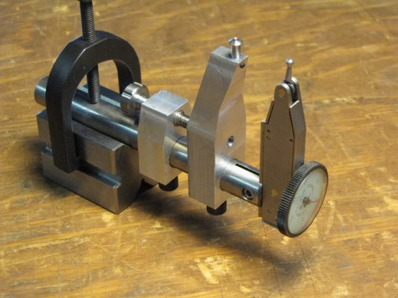


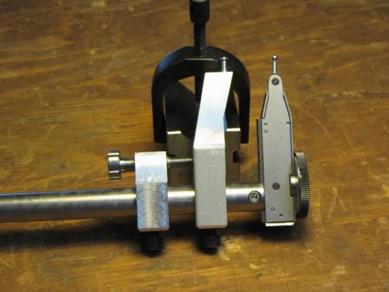
and a side view of the gage.


This tool cried out to me for a vernier fine adjustment and, feeling the need to personalize the project, I added one.  It acts similar to the sort used on beam compasses but, instead of a simple threaded shaft uses a differential screw.

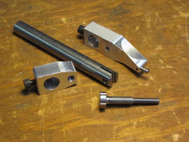
As is apparent in the next picture, the differential screw is threaded with two different threads.  The body that threads into the vernier guide is 1/4-40 and the end which threads into the movable arm is threaded 10-32.

With this arrangement, one turn of the vernier adjustment knob will move the movable arm by:

1/32 - 1/40 = 1/160 = 0.00625"

the equivalent of a 160 tpi thread.  With six notches on the knob, a one notch movement is very close to one thousandth of an inch movement.


The next photo shows the dovetail that secures the DTI in the end of the rod.  To make it, I slotted with a 3/16" endmill to the correct depth and then cut the dovetail with a 1/4" dovetail cutter that I purchased from Brownells, the gunsmith suppliers in Iowa.  Such tiny cutters are used to cut the dovetails used to secure the (adjustable) front sight on some types of firearms.

http://www.brownells.com/
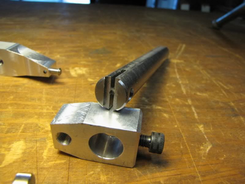


[Another aside:  As made, the adjusting screw is backwards.  A clockwise turn of the screw will move the movable arm toward rather than away from the vernier guide.  Were the 32 and 40 tpi sections reversed, this would be rectified but I was using dies and wanted a one piece screw so accepted the reversed movement which doesn't annoy me anyway.  However, be warned if you make your own differential screws - think it through first.

If you want help with the mathematics of designing differential screws, there's a program on my page titled, surprisingly, DIFFTHRD that will be of assistance.]
Regards, Marv

Home Shop Freeware
https://www.myvirtualnetwork.com/mklotz

Offline Bernd

  • Madmodder Committee
  • Hero Member
  • *****
  • Posts: 3688
  • Country: us
  • 1915 C Cab
    • Kingstone Model Works
Re: Vernier bore gage
« Reply #1 on: September 11, 2009, 07:21:13 PM »
Marv,

Great design. Now I went and looked at the thread on HMEM. I saw that mics were used on two of the setups shown. I would think a ring gage would be more accurate than using mics. But then how close are we measuring anyway?

Bernd

Edit: Just got back from HMEM forum and found George's answer to a ring gage. Use a standard bearing. Use the id of the bearing to set the gage up. Marvelous.
« Last Edit: September 12, 2009, 08:52:46 AM by Bernd »
Route of the Black Diamonds

Offline sbwhart

  • Global Moderator
  • Hero Member
  • *****
  • Posts: 3530
  • Country: gb
  • Smile, Be Happy, Have Fun and Rock Until you Drop
Re: Vernier bore gage
« Reply #2 on: September 12, 2009, 02:00:48 AM »
Hi Marv

Thats a great design I like the differential screw still trying to get my head round why things reverse  :scratch: I'll keep thinking about it and the penny will drop, thats what's so great about this game keeps the little gray cells working  :hammer:.

I've got some close bore work to do on another project so I may knock one of these up to help the process.

Thanks for sharing

Stew
A little bit of clearance never got in the road
 :wave:

Location:- Crewe Cheshire

Offline mklotz

  • Sr. Member
  • ****
  • Posts: 260
  • Country: us
  • LA, CA, USA
    • Software For People Who Build Things
Re: Vernier bore gage
« Reply #3 on: September 12, 2009, 10:41:41 AM »
Why things reverse...

The vernier guide (smaller piece) is fixed to the rod by its setscrew.  The movable arm is free to, well, move.

Now, one turn of the differential screw will cause the movable arm to move forward by 1/40 inch.  At the same time, this turn of the screw (sorry, Henry) will move the movable arm backward (i.e., toward the vernier guide) by 1/32 inch.  Since 1/32 is greater than 1/40, the movable arm moves backward by an amount equal to the difference, 1/32 - 1/40 = 1/160.

Now, as a gedankenexperiment, imagine the threadings on the screw interchanged and convince yourself that, if that were the case, one turn of the screw would move the movable arm forward.
Regards, Marv

Home Shop Freeware
https://www.myvirtualnetwork.com/mklotz

Offline sbwhart

  • Global Moderator
  • Hero Member
  • *****
  • Posts: 3530
  • Country: gb
  • Smile, Be Happy, Have Fun and Rock Until you Drop
Re: Vernier bore gage
« Reply #4 on: September 12, 2009, 01:03:18 PM »
Penny's dropped thanks for that  :thumbup:

Stew
A little bit of clearance never got in the road
 :wave:

Location:- Crewe Cheshire