Author Topic: Bog's Paddleduck Engine  (Read 98681 times)

Offline kvom

  • Hero Member
  • *****
  • Posts: 520
Re: Bog's Paddleduck Engine
« Reply #25 on: May 02, 2009, 12:30:04 PM »
I did a few calculations around the crank webs and the connecting rod.  I have access to a goodly amount of .25" thick brass plate, so I'm planning to cut the webs from that, although proportionally it's undersized.  Given the spacing between the pillow blocks, the crank end of the connecting rod would need to be increased somewhat, to ~.45".  Since I just ordered a stick of .5" square brass rod, that seems the way to go.

So this morning I cut out a roughly 1.8" square of the plate with a hacksaw, drilled a 1/4" hole in the center, and turned it down on the lathe using the same clamping method as for the eccentric.  It took a few tries to figure out the best clamping method, but eventually I arrived.  It would be quicker all around just to mill out the discs with a rotab, however.

bogstandard

  • Guest
Re: Bog's Paddleduck Engine
« Reply #26 on: May 02, 2009, 01:28:43 PM »
Kvom,

I couldn't understand the way you are going to take up the missing space, so either make the crank blocks longer (expensive), or put a spacer in between the crank webs and blocks to take up the side slack.


John

Offline kvom

  • Hero Member
  • *****
  • Posts: 520
Re: Bog's Paddleduck Engine
« Reply #27 on: May 02, 2009, 01:44:34 PM »
On the plan, webs are 5mm and conrod is 6.5, so 16.5mm.  Scaling up this gives .974" of material.  If my webs are .25" each, then the conrod end would be .474" to give the same spacing.  This is opposed to the .384" it would normally be.  Since I'm starting with a .5" square bar, I won't need to add a spacer.

***edit***

I made the second disc using the Palmgren (copy)? rotab, cutting it out using a 1/8" 4-flute endmill, the smallest I own.  No real problems, other than the usual hassle of clamping small pieces with big clamps and bolts.

I'm now out of pieces large enough, so will need to resupply on Monday night.  I think I know a better way to do the other two.

I'm wondering if the 1/8 endmill is too wide for slitting the webs?  Opinions?
« Last Edit: May 02, 2009, 04:23:53 PM by kvom »

Offline sbwhart

  • Global Moderator
  • Hero Member
  • *****
  • Posts: 3530
  • Country: gb
  • Smile, Be Happy, Have Fun and Rock Until you Drop
Re: Bog's Paddleduck Engine
« Reply #28 on: May 02, 2009, 06:43:43 PM »
Try a 1/16" slitting saw if you've got one, it would look more in scale.

Stew
A little bit of clearance never got in the road
 :wave:

Location:- Crewe Cheshire

Offline kvom

  • Hero Member
  • *****
  • Posts: 520
Re: Bog's Paddleduck Engine
« Reply #29 on: May 02, 2009, 09:20:02 PM »
I spent a couple of hours in the shop after dinner starting on the packing gland.

For the screws, I decided to use a diameter of 15/32 so that later, when I need to turn the flange to fit the cylinders and drill for the piston rods, I will be able to hold the glamd in a collet rather than the chuck.  The thread is 3/8-16.  I had no real issues turning the screws as I had a piece of 1/2" brass rod to start with.

I then turned the gland itself, with the inner diameter 15/32 to match the screw, and the outer diameter 1", turned from a piece of 1" brass rod (took .001 off for finish).  Then drilled and tapped to match the screw.  After parting there is enough extra length left to turn the inner boss for the cylinder bore.

My only "problem" is that the screw won't go in all the way, because the tap won't cut enough threads (pointed part is too long).  If I can find a bottoming tap at school I'll fix it that way; otherwise I can always shorted the screw portion.

Thoughts?

I finished only one gland, so the other is on the agenda for next time.

Offline kvom

  • Hero Member
  • *****
  • Posts: 520
Re: Bog's Paddleduck Engine
« Reply #30 on: May 03, 2009, 08:30:28 PM »
I ground the tip off the tap and was able to get the threads deeper into the gland.

Unfortunately I discovered that one of the screws goes in slightly crooked, so I'm pretty sure that means a redo on that one.  And then I screwed up the straight one milling the side flats, so that's a redo as well.  :hammer:  I think it's going to be preferable to mill the flats before parting off the screw, as then I can mount the rod in a 5c collet in the square collet block for milling.

I did find one more piece of brass big enough for a crank web, so now I have three - one to go.

Offline kvom

  • Hero Member
  • *****
  • Posts: 520
Re: Bog's Paddleduck Engine
« Reply #31 on: May 04, 2009, 03:24:47 PM »
A little progress this afternoon:

Reading through the book I noticed that the valve packing gland is almost identical to the piston gland (flange is a bit smaller).  So since the 1" round stock was still chucked in the lathe, I turned two of these.  I left the flange diameters to be turned down when the boss for the bore is turned.

I found out that my class is cancelled for tonight, so I won't be able to get any more brass material until Thursday, unless UPS arrives with the 1/2" bar I ordered.

I decided I could make the plain pipe flange from the 1" round stock.  I chucked the bar in the billing vise using v-blocks and cut the flats wide wide enough for two flanges.  Then I chucked the bar in the lathe and drilled it assuming 1/4" pipe.


Then it was just a matter of turning it down to the correct diameter and parting off.


Looking at the photo it seems they're slighly unbalanced, but I can correct that when it's time to drill the mounting holes.

Given the larger size, I'm wondering if brass will be strong enough to make the long flanges.  I may try to make a couple.

Offline kvom

  • Hero Member
  • *****
  • Posts: 520
Re: Bog's Paddleduck Engine
« Reply #32 on: May 04, 2009, 09:36:02 PM »
Spent the evening making 4 identical packing gland screws.  Mounted a 1/2" brass rod securely in the square collet block in the milling vise.  This allowed me to mill flats on opposite sides for all 4 screws.  The flats fit a 3/8" wrench.


Then I chucked the bar in the lathe and turned the OD to 15/32.  Then for each screw:
 - turn the end section to be threaded to .370" for 3/8-16 threads
 - undercut the end of the threaded section at the head
 - single point the threaded section on the lathe to a thread depth of .06"
 - finish the thread form with a die
 - test fit to a gland for good measure
 - part off

Took about 1:15 for the 4 pieces


Offline kvom

  • Hero Member
  • *****
  • Posts: 520
Re: Bog's Paddleduck Engine
« Reply #33 on: May 05, 2009, 06:29:57 PM »
After lookomng at the drawings and measurements once more, it looks as if the 1.5x goal has put me into the "expensive materials" category, as the block will be just over 3" long and 2" high.  Trying to find brass with those dimensions doesn't appear straightforward.

I am thinking it should be possible to make two separate cylinder blocks.  Any reason that won't work?

Offline DavesWimshurst

  • Jr. Member
  • **
  • Posts: 68
Re: Bog's Paddleduck Engine
« Reply #34 on: May 05, 2009, 11:42:18 PM »
Kvom,
I'm building the same engine in approximate 1-1 scale with colonial imperial threads.
Perhaps cast iron for the block would be possible using 1 inch thick bar stock which is a little thin
http://www.mcmaster.com/#cast-ductile-iron/=1qzvag
or use brass or bronze liners in an aluminum block.
Dave

bogstandard

  • Guest
Re: Bog's Paddleduck Engine
« Reply #35 on: May 06, 2009, 12:07:11 AM »
Kvom,

Are you going for steam or air driven?

I keep asking this question, but it does mean that if you are only going to run on air, then almost anything will do for the main cylinders, even something like nylon could be used if you can get nice smooth bores. I would suggest a nice cheap material like free cutting mild steel. EN1a here in the UK, or ali.

But if going for steam, then cast iron, bronze or brass should be your first choices.

I have included a C-o-C for perusal.

The central mounting bolts do play an important part in the makeup of the engine, in that they stabilise the central portion of the top mounting plate.

But if you can get the hole pattern in like is shown in the bottom sketch, that will do almost the same job, and I wouldn't envisage any flexing problems.

If running on steam, in fact, having a gap between the cylinders will help in the steaming qualities of the engine. It will allow the engine to warm up a lot quicker and produce less condensate. Have a look at how I have seperated the cylinders on the 'blinged' one. That reduces the mass for the steam to warm up, but still retains the one block principle.

Before doing all your final 'exact' calculations for the cylinder bores, settle on a size that matches generally available o-rings. The engine will run quite happily without rings on either steam or air if a couple or three fine oil grooves are put around the piston, but again, if you want to fit rings, if just air, anything will do, but again, with steam, the choice is limited to either Viton (recommended) or silicon (not recommended if WD40 or most other spirits are coming into contact with the engine for cleaning).

I hope this helps you in some way.


Bogs
« Last Edit: May 06, 2009, 12:15:52 AM by bogstandard »

Offline ozzie46

  • Sr. Member
  • ****
  • Posts: 260
  • Country: us
Re: Bog's Paddleduck Engine
« Reply #36 on: May 06, 2009, 07:06:39 AM »


  John I am building this too. but am have truoble getting a good finish on the bore. I am using imperial and made my cyl 3/8, how big can I ream them and not effect performance?


  Ron

Offline kvom

  • Hero Member
  • *****
  • Posts: 520
Re: Bog's Paddleduck Engine
« Reply #37 on: May 06, 2009, 08:37:09 AM »
I will be running strictly on air, and using an oiler-regulator for lube rather than the displacement oiler.  For that reason I also plan to make the handle on the control block more like a manual one.  I plan to make the pistons from aluminum with oil grooves rather than rings.

I am really wanting to have an "all brass" engine for the look.  I could definitely change the mounting hole pattern for more stability.  I do have a block of a reddish brass alloy at school that might work, but will have to wait until tomorrow night to get a measurement.  It's the same material from which I made the cylinder for my beam engine; someone thought it might be beryllium-copper.

In the meantime I got my 1/2" brass bar yesterday and now have plenty to do making the connecting rods and couplings.  Especially since we are having a nice thuderstorm at the moment, so outdoor activites are off for the day.

Thanks for all the ideas.
« Last Edit: May 06, 2009, 08:41:11 AM by kvom »

Offline sbwhart

  • Global Moderator
  • Hero Member
  • *****
  • Posts: 3530
  • Country: gb
  • Smile, Be Happy, Have Fun and Rock Until you Drop
Re: Bog's Paddleduck Engine
« Reply #38 on: May 06, 2009, 09:02:22 AM »
I will be running strictly on air, and using an oiler-regulator for lube rather than the displacement oiler. 

Just out of interest whats an oiler-regulator  :scratch:  its a term I've not come across before.

Thanks

Stew
A little bit of clearance never got in the road
 :wave:

Location:- Crewe Cheshire

Offline Bernd

  • Madmodder Committee
  • Hero Member
  • *****
  • Posts: 3688
  • Country: us
  • 1915 C Cab
    • Kingstone Model Works
Re: Bog's Paddleduck Engine
« Reply #39 on: May 06, 2009, 09:18:57 AM »
Stew,

Trying to figure out how to tell this. It's sort of a small container that is added on after the one that removes water from an air compressor. The unit allows you to adjust the drops of oil into an air line to lubricate air powered tools. I'm sure you've seen them before, it's just our two languages again causing the problem. :)

regards,
Bernd
Route of the Black Diamonds

Offline sbwhart

  • Global Moderator
  • Hero Member
  • *****
  • Posts: 3530
  • Country: gb
  • Smile, Be Happy, Have Fun and Rock Until you Drop
Re: Bog's Paddleduck Engine
« Reply #40 on: May 06, 2009, 09:38:50 AM »
Thanks Bernd

That sorted me out  :thumbup:

Stew
« Last Edit: May 06, 2009, 10:29:43 AM by sbwhart »
A little bit of clearance never got in the road
 :wave:

Location:- Crewe Cheshire

bogstandard

  • Guest
Re: Bog's Paddleduck Engine
« Reply #41 on: May 06, 2009, 10:19:23 AM »
Ron,

You can go as large as you need to, but keep an eye on the flange mounting screws at the end of each bore, don't go too close to the screw holes as they might weaken and strip out if you get too close. Just make the spigots on the flanges to fit the larger bores and of course, the pistons.

Kvom,

Be very careful machining it if it is beryllium copper, it releases some nasty things when machined under certain circumstances. I would have a look on the web for info on how to treat it while machining. It is always better to be on the safe side.

John

Offline kvom

  • Hero Member
  • *****
  • Posts: 520
Tough afternoon in the shop
« Reply #42 on: May 06, 2009, 05:24:35 PM »
I don't have much to show for 4+ hours of work.


My first goal was to mill the brass to size for the conrods, but I was having all sort of problems with the finish.  After changing endmills a few times without success, I noticed a little light on the control panel of the VFD : rev.  I had been running the spindle in reverse.   :hammer:  This is not something that would be likely to happen using the normal mill switch.  Either I left it in reverse after boring the eccentric straps in back gear, or I fat-fingered the button (which is right above the run button.  As I was running the mill at 2000 RPM I didn't really notice that it was turning back-asswards.

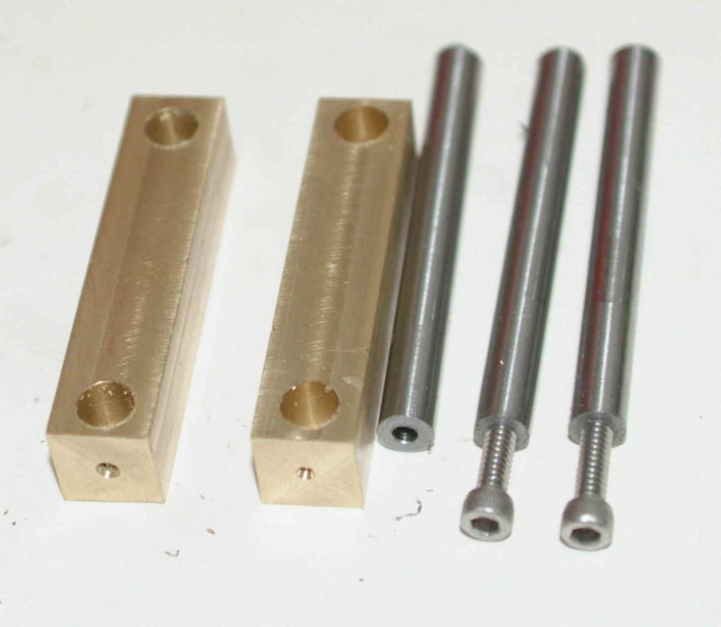
So after wating a fair amount of time I did manage to mill the brass to size, center drill the ends, and drill/ream the holes at 1/4".  My intention is to turn the conrod like John's, between centers.  Since I need to borrow a lathe dog from school to do this I'm leaving the rest of the milling for afterwards.

I then decided to make the crosshead guide bars from some 1/4" drill rod.  After some calculations on dimensions I settled on drilling and tapping the ends for 6-32 screws.  Rather than mess around with the collet blocks to hold the rod, I switched to the rubberflex collet chuck.  Drilling the rods was not much of a problem.  However, when I attempted to tap the first one still chucked, I broke my automotive-quality tap off in the hole.  I was able to extract the tap, and decided to tap the rods later using the mill as a tapping station.  This rod didn't take will to parting either, as once the parting bit is halfway through the rod snaps off, and also causes the chucked end to bend at the chuck jaws.  So after the first one, I just used the DRO to mark the length, parted just enough to show where to cut, and cut it off with a hacksaw.

Now that I had the 4 drilled pieces, I proceeded to tap them at the mill.  The first two went fine, but on the third I snapped off my only remaining, good quality, 6-32 tap.  So that was then end of that for now.   :bang:

I decided it was time to take a break. 

Perhaps I need to anneal these rods before tapping!?
« Last Edit: May 06, 2009, 05:26:45 PM by kvom »

Offline Darren

  • Madmodder Committee
  • Hero Member
  • *****
  • Posts: 3795
  • N/Wales
Re: Bog's Paddleduck Engine
« Reply #43 on: May 06, 2009, 07:13:02 PM »
Thank you for posting that, I was feeling quite left out.......... :ddb:

Amaizing how it still mills backwards.... :doh: But you look like you are winning  :clap:
You will find it a distinct help… if you know and look as if you know what you are doing. (IRS training manual)

Offline kvom

  • Hero Member
  • *****
  • Posts: 520
Re: Bog's Paddleduck Engine
« Reply #44 on: May 07, 2009, 07:29:05 PM »
This morning I attempted to machine an eccentric coupling fork.  Unfortunately when I started to mill the slot I discovered that a 1/4" slot is too wide.  It scales to .236.  And in addition my 1/4" end mill is slightly oversize as well.  So on to a redo with the 1/8" endmill.  On the bright side I came to undestand that it's quicker to square off the stock for both forks at the same time and then cut them apart.   :smart:

I had an excellent trip to school this afternoon to discuss my engine issues with the instructor, and to borrow some needed gear.  So to total it all up:

- He recommended that for tapping the drill rod for the crosshead guides, I should drill the hole with 1 or 2 sizes up on the drill bit and somewhat deeper.  That will lessen the chance that I will break the tap (and I got a new tap to try it with).

- borrowed a 1/16" slitting saw on an R8 arbor for slitting the crankwebs.  Here he suggested that clamping all 4 of the discs together and slitting them at one time might make for a more rigid setup.  By leaving the pins in the holes used for milling level, the setup can be the same, and the pins removed as the saw blade nears the hole.  He suggested slow RPM and slow feed.

- Borrowed 2 lathe dogs for turning the conrods between centers (looks as if either will work).  I also got a piece of steel from which I plan to make an adjustable dog that fits my chuck.

- scored a piece of brass plate 1/4" x 3" x 8" that will serve to make the bottom plate, the 4th crankweb, and some of the other smaller plates as well.

- Found that the block of mystery brass alloy in my lockers is large enough for the block, and possibly even two of them.  Another piece of the same allow can make all 4 bearing blocks.

- The 2" round silver brass that Cedge gave me will get a slice cut off for the flywheel.

So it looks as if I am set for material except for the top plate.  But there is a fellow on eBay who sells pieces that will be suitable.

Nothing stopping me at the moment but lack of energy.   :whip:

Here's the result of the evening's efforts.  Two forks for the eccwentric coupling.  Haven't drilled the holes for the pins as yet.

« Last Edit: May 07, 2009, 10:05:23 PM by kvom »

Offline kvom

  • Hero Member
  • *****
  • Posts: 520
Question for John
« Reply #45 on: May 07, 2009, 10:25:16 PM »
I can't seem to find a description of the threaded adjuster that connects the eccentric fork to the spool valve.  Can you point me to the right spot in the book?  Or is iit just a length of threaded rod with a jam nut?

bogstandard

  • Guest
Re: Bog's Paddleduck Engine
« Reply #46 on: May 08, 2009, 12:19:44 AM »
Kvom,

Here is the description, not much, so that might be why you couldn't find it.

Yes it is just a bit of threaded rod and a locknut.


Bogs

Offline kvom

  • Hero Member
  • *****
  • Posts: 520
Re: Bog's Paddleduck Engine
« Reply #47 on: May 08, 2009, 06:04:29 PM »
I did some measurements and discovered that I indeed have enough brass for both the top and bottom plates, so as of now the only material I am missing, AFAIK, is the correct diameter drill rod for the spool valves.

My first task this morning was to cut the ~6"x3" bottom plate blank out of a 9x4 piece of 1/4" brass.  I could have done this on the bandsaw, but decided to mill it out with a 1/8" endmill.  It took longer, but in the end I wasted less material.  From the cutoff, I then cut out a piece big enough to turn the disc for the 4th crankweb.  My boo-boo was to crank it a little too hard and broke the endmill.  Luckily it's a double ended mill, so I still have one to go.

I was going to post in detail about another fubar I did, but I'll just summarize it by stating that when tapping a hole, look to see that you do indeed have the correct size tap in the tap wrench.   :hammer:

After lunch I tackled the crankwebs, now that I had all 4 discs cut out.  Drilled the holes and pressed in the drill rod.  I am using 1/4" for both shaft and pin:


My little arbor press was handy here.  Milled the first side:


I used a 3/8" ball-end mill to get the rounded inner corner.  Then the other side:


All ready to be slit:


I'm not sure whether to drill and tap the lock screw before slitting.   

bogstandard

  • Guest
Re: Bog's Paddleduck Engine
« Reply #48 on: May 08, 2009, 10:17:06 PM »
Kvom,

Wait until after slitting, then just drill all the way thru with your tapping drill, then using your clearance drill, go down until it reaches the slot. Then cut the thread. It save lots of trouble finding the correct depths to drill to.


Bogs

Offline kvom

  • Hero Member
  • *****
  • Posts: 520
Re: Bog's Paddleduck Engine
« Reply #49 on: May 09, 2009, 08:58:29 PM »
Yesterday evening I had squared up the base plate and flycut the top surface.  As it was still in the vise this evening I continued to drill the holes in the plate.  After center drilling all of them, I came to the conclusion that the scaled metric screw for the bearing blocks was between a 6-32 and an 8-32  SAE.  Since these are not visible, I decided to go with the larger screw.  I used a #20 drill bit for the 8 inner holes, leaving ~.003" clearance.  Since my parallels were under the points for the perimeter holes I decided to defer drilling these.  I'm not sure how I will be mounting the finished engine. 

I then proceeded to slit yesterdays crank webs using the borrowed slitting saw/arbor.  This went nicely and quick fast.  I used the same drill rods in the holes to clamp the webs parallel to the top of the vise jaws.  The mill was running in back gear at 200 rpm with a feed rate < 1ft/min.  The exposed radius of the saw was "just" enough to reach the small end hole.

Having been out and about in the sun all day I decided I was sufficiently tired to call it an evening, before I did something silly.