Author Topic: Desktop Mill CNC Conversion  (Read 17797 times)

Offline Joules

  • Hero Member
  • *****
  • Posts: 1268
  • Country: gb
Re: Desktop Mill CNC Conversion
« Reply #25 on: September 24, 2016, 01:20:39 PM »
 :bugeye:   Those holes look like they were formed with artillery shells, round they are not.  They all got diamond stoned so they are recessed a little.  I used a straight edge to check for light across the centre of the casting, its pretty flat despite the blueing appearance.  I'm not too worried about perpendicularity, the outfit that machined it weren't   

:jaw:
Honour your mentors, and pay it forward.

Offline Will_D

  • Hero Member
  • *****
  • Posts: 668
  • Country: ie
    • National Homebrew Club of Ireland
Re: Desktop Mill CNC Conversion
« Reply #26 on: September 25, 2016, 06:21:29 PM »
Hi Joules,

Well my pendant arrived and after weaving a rats nest of wires on my desk it all works!

Now all I have to do is put the Controller, PSU and drivers in a nice housing, fit at least 4 Cannon D-type connectors ( Pendant and 3 axes (Power and limit switches to the axes)) and make the internals look pretty!)

Progress is being made on the SX2P conversion to manual/MPG'd X and Y axis operation. Not sure if I will bite the JS bullet and mod the Z head (as per ME website)

Cheers

Will
Engineer and Chemist to the NHC.ie
http://www.nationalhomebrewclub.ie/forum/

Offline Joules

  • Hero Member
  • *****
  • Posts: 1268
  • Country: gb
Re: Desktop Mill CNC Conversion
« Reply #27 on: September 28, 2016, 04:45:38 PM »
I have the column and knee sorted now, still more flex than I would like but it seems to be a FEATURE of this machine.   Will have to see how that translates into the quality of work I can get out of it.

Next up is finding out the error in the horizontal spindle position.  First job check my table is tracking level in Y


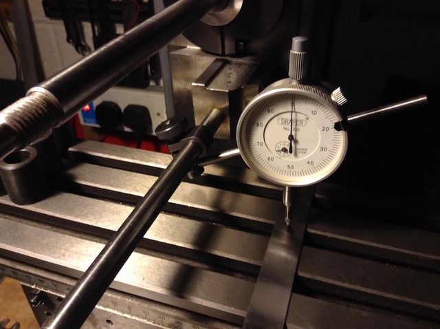
Happy with that, 0 end to end, now to clock the horizontal spindle after clocking it runs true along in's length, and it does.


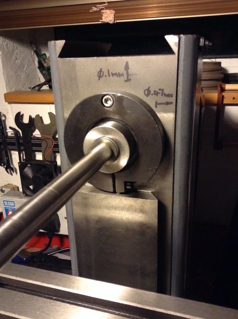
The spindle is pointing up 0.1mm over 170mm of travel.


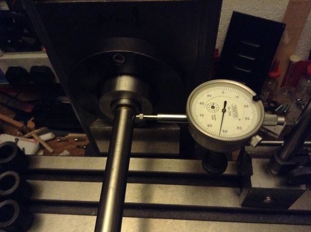
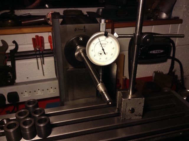
OK I screwed up as I should have zeroed from the spindle out but zeroed at the end of the spindle and clocked inwards.  Thats 0.47mm pointing right   :(   again over 170mm, not as bad as I was expecting, but still plenty to give the overarm bearing a hard time, not to mention the unnecessary load on the spindle bearings.


So this is where I am up to now, I need to turn a small shaft or mount my laser alignment tool in the overarm bearing to check the spindle centre is where it should be and that the runout is at the rear, as it appears to be in the casting.  Work out a plan and do another tear down, I think I can do this in my sleep now.

I just realised this should probably have been posted in Project Logs till I get to the actual CNC conversion.  Hope it's useful info for someone.
Honour your mentors, and pay it forward.

Offline DICKEYBIRD

  • Full Member
  • ***
  • Posts: 229
  • Country: us
  • Collierville, TN ya'll
Re: Desktop Mill CNC Conversion
« Reply #28 on: September 28, 2016, 06:19:28 PM »
I don't have one of those cool little mills myself Joules but always enjoy watching you work.  Keep it coming, I'll be here! :beer:

Milton in Tennessee
Milton in Tennesee

"Accuracy is the sum total of your compensating mistakes."

Offline Joules

  • Hero Member
  • *****
  • Posts: 1268
  • Country: gb
Re: Desktop Mill CNC Conversion
« Reply #29 on: September 29, 2016, 07:07:57 AM »
I should have included in my description that the table doesn't have 170mm of travel in Y, so the trick is start at one end and travel along the spindle to a mark around midpoint.  Take a reading, reposition the clock and table to continue clocking the spindle having set the clock to the midpoint reading.  Then complete the travel arriving at your final value.  OK, it does allow for some error to creep in, but nothing like the value I am seeing, I should also add a bit of tongue in cheek tolerance for my cheap dial gauge, so the figures are approximate.  I can check the dial against my height gauge later on the new surface plate.

Taking careful note of Milton's signature.
Honour your mentors, and pay it forward.

Offline lesterhawksby

  • Jr. Member
  • **
  • Posts: 36
Re: Desktop Mill CNC Conversion
« Reply #30 on: September 29, 2016, 01:02:03 PM »
I'm somewhat embarrassed by how rough that thing is. I did try to warn Joules how bad the horizontal was!

(I only used it as a vertical and, actually, it cut some fairly smooth and square surfaces for me on small parts despite the poor contact Joules has discovered - I never stripped it down and built it up properly when I got it - but I spotted the horizontal problem early and fixing it is beyond me. Various misadventures in outside-the-shop life prevented me from taking it back when I first found out)