Author Topic: Modified Rocking Engine  (Read 46487 times)

Offline NickG

  • Madmodder Committee
  • Hero Member
  • *****
  • Posts: 1890
Re: Modified Rocking Engine
« Reply #25 on: September 09, 2009, 04:56:53 AM »
Plan for tonight is to get this frame finished and possibly do the bearing! But you've seen my outlandish claims before and by now probably realise I'll only get the frame done!
 :poke:
Nick
Location: County Durham (North East England)

Offline NickG

  • Madmodder Committee
  • Hero Member
  • *****
  • Posts: 1890
Re: Modified Rocking Engine
« Reply #26 on: September 10, 2009, 03:52:44 AM »
Hi,

Didn't get the bearing done. Had a busy night. Badminton, then England game which I forgot about - what a result by the way, then 3 hours in the shop! I got the frame finished but it was 1am by that time so was too tired for the write up! Will have to be a double installment tonight!

No more milling left on this project except for the wooden base, got the bearing, crankshaft, flyhweel, piston, inlet nozzle, & two pedestals to do along with the base.

At least I have a bit of an assembly to show now, starting to look like an engine of sorts!

Nick
Location: County Durham (North East England)

Offline NickG

  • Madmodder Committee
  • Hero Member
  • *****
  • Posts: 1890
Re: Modified Rocking Engine
« Reply #27 on: September 10, 2009, 07:43:49 PM »
Hi,
Bit more progress tonight, I’ve done the bearing. Starting to look like something now.
Here are some pics from last night doing the frame and tonight the bearing.

Set up in mill for drilling holes. Tried marking out with the blue this time, worked well I thought.


After holes were centre drilled I cut the radius on the corner, opened out the bearing hole and tapped 5/16 x 32 TPI. I actually did this under power. Never tried that before, the mill has a 1000W DC motor and even at just a few rpm I couldn’t stop the spindle with my hand. I didn’t go mad tightening the tap in the collet incase it jammed, this way the tap would just slip inside the collet. It was fine though, tapped a nice thread which surprised me in this soft aluminium.

Then I opened the two bolting holes to tapping size. You’ll see why later.


Holes were drilled and tapped in bottom for pedestal support thingies! I made the mistake of trying to tap these under power too, big no no, was much smaller 4ba thread and I managed to mess up the top of the thread on one hole, luckily I stopped in time and there are enough good threads underneath.


This is why I only drilled the bolt holes tapping size, so I could accurately transfer to the other half of the frame.


Once this was done I could open them to 4 ba clearance size.


That was the frame finished then.

Tonight’s exercise was to make the bearing. I faffed around for ages trying to find a  bit of brass, at one point I thought I was going to have to turn down some square, but then I found a big length of about  ½” or 5/8” brass hex that I was allowed to take home from work!


Turning down to size


Cut  5/16” x 32 tpi thread, I just used a die for this applying light pressure with the tailstock to keep it straight.


Drill the hole for the crankshaft with no 12 drill. The size is not mega critical since I will turn the crankshaft to suit.


Part off to length under power after making an undercut on thread.


The bearing:


Tightening bearing into frame in chuck so I can drill oil hole in correct place.


Oil hole drilled, csk and all completed components test assembled.


Sorry about the quality of these pictures. Really need a better camera or learn how to use existing one better!
Note I didn’t tighten the bearing back in since it all needs to come to bits to be cleaned, so the oil hole looks wonky!
Quite pleased so far, if I can keep this standard of finish and fit up I’ll be chuffed, if of course it works! (Touch wood)

Nick
Location: County Durham (North East England)

Offline sbwhart

  • Global Moderator
  • Hero Member
  • *****
  • Posts: 3530
  • Country: gb
  • Smile, Be Happy, Have Fun and Rock Until you Drop
Re: Modified Rocking Engine
« Reply #28 on: September 11, 2009, 01:12:04 AM »
Looking good Nick

Stew
A little bit of clearance never got in the road
 :wave:

Location:- Crewe Cheshire

Offline spuddevans

  • Global Moderator
  • Hero Member
  • *****
  • Posts: 1618
  • Country: 00
  • Portadown, Northern Ireland
    • My Photo website
Re: Modified Rocking Engine
« Reply #29 on: September 11, 2009, 01:57:47 AM »
That's looking really good, you'll have a runner there before long  :thumbup:


Tim
Measure with a micrometer, mark with chalk, cut with an axe  -  MI0TME

Offline NickG

  • Madmodder Committee
  • Hero Member
  • *****
  • Posts: 1890
Re: Modified Rocking Engine
« Reply #30 on: September 11, 2009, 03:57:13 AM »
Do be totally honest, I'm not convinced whether it will run. After I started I got thinking about how i'd designed it. I'm not sure whether I've made the conrod too long, hence on the return stroke the piston might not rock to a large enough angle to vent sufficiently. The problem this could cause is that there is still too much force on the piston for the flywheel to carry it over to the next power stroke. The air should find the easiest route but it just depends on that balance of forces. Need  :smart: really! This may be why the small bore ones are so effective too. You can see that if you put the pressure too high, it won't carry over so low pressure might be the order of the day.

Time will tell,  :zap: it could be back to  :coffee:  :lol: to fix it I may be able to shorten the frame, reposition the bearing and shorten the piston rod - well, that means a new piston as it's 1 piece in my design. Unless I keep a plain diameter for the piston rod until I have it running instead of wasting away the section between the big end and the piston.

Nick
Location: County Durham (North East England)

Offline Stilldrillin

  • Global Moderator
  • Hero Member
  • *****
  • Posts: 4972
  • Country: gb
  • Staveley, Derbyshire. England.
Re: Modified Rocking Engine
« Reply #31 on: September 11, 2009, 12:49:44 PM »
Nick,

It WILL run! Relatively slowly, mebbe........ Have faith......  :thumbup:

David D

David.

Still drilling holes... Sometimes, in the right place!

Still modifying bits of metal... Occasionally, making an improvement!

Offline rleete

  • Madmodder Committee
  • Hero Member
  • *****
  • Posts: 534
  • Country: us
Re: Modified Rocking Engine
« Reply #32 on: September 11, 2009, 01:00:05 PM »
I'm not convinced whether it will run.

I've found my rocker to be very forgiving, and actually runs a lot better not that it's loosened up.  As long as the piston doesn't come out of the bore on the back stroke, or bottom out, it should be fine.
Creating scrap, one part at a time

Offline NickG

  • Madmodder Committee
  • Hero Member
  • *****
  • Posts: 1890
Re: Modified Rocking Engine
« Reply #33 on: September 11, 2009, 01:36:14 PM »
Will have to see, because I've changed the parameters. I might not have heavy enough flywheel relative to the bore and stroke, and I might not have designed it to 'rock' the piston enough. I maybe should have scaled this part from a known working one, but I just did it where it looked right to me. I'm about 50% certain it'll run  :lol:

Hopefully will get a bit more done tonight. Not sure what to start on though, should I tackle the crankshaft, probably the most complex turning job if doing it in 1 piece, should I do the inlet .. should be straight forward but quite interesting with the taper and the steps, should I do the 2 pedestals ... was a bit fiddley first time around. could do the piston I suppose, then I can turn the crankpin for a good fit in the big end. Or the wooden base?! Decisions decisions ...don't suppose it matters really, all needs to be done!!!

What will it be... come back tomorrow or very late tonight to find out!  :lol:

Nick
Location: County Durham (North East England)

Offline NickG

  • Madmodder Committee
  • Hero Member
  • *****
  • Posts: 1890
Re: Modified Rocking Engine
« Reply #34 on: September 11, 2009, 01:38:26 PM »
PS, forgot an important bit ... don't think it'll run without a flywheel!  :lol: Not doing that tonight though, can't be @rsed to hand saw through 2" of steel, not sure how well it would part off.

NIck
Location: County Durham (North East England)

bogstandard

  • Guest
Re: Modified Rocking Engine
« Reply #35 on: September 11, 2009, 02:33:43 PM »
Nick,

Don't rush it, I made that mistake yesterday, and cost me a couple of hours machining time, plus a bit of material.

It isn't going to get up and run away (unless you've got gremlins in your shop). Just take your time and do it at your own pace.


Bogs

Offline NickG

  • Madmodder Committee
  • Hero Member
  • *****
  • Posts: 1890
Re: Modified Rocking Engine
« Reply #36 on: September 11, 2009, 07:07:09 PM »
Hi all,

You're right Bogs, I need to calm down a bit. It doesn't really matter if it takes another week or another month, hence I've come in at 10:30 - pratted around on internet for an hour instead of writing this up and now I'm tired! :bang: It just initially annoyed me when I got back in the shop after a while off as I’m used to the alarming rate people churn things out on here!  :poke:

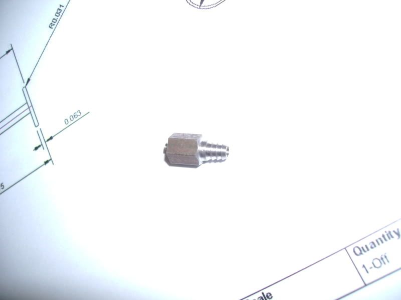
Tonight I just made the inlet nozzle. I had to do a couple of modifications on the fly. The first was that I had run out of my 5/16" hex brass bar. I knew I had some quarter inch steel hex so looked for that. To be honest, 5/16" would have been too big in any case. The 2nd mod before I even started was to change the hole through it from 1/8" to 3/32". Looking at the drawing it was getting a bit too thin at the front of the nozzle with the 1/8" hole. I will update the drawings to reflect this if it works, then other people can have a go if it's any good.

I decided it’d be best to do the nozzle end first, can’t remember why, but this turned out to be a mistake! Will get on to that in a min!

Must apologise again for the quality of some of these photos, I just haven’t got the light right or something but don’t really have time to mess around with that at the mo.

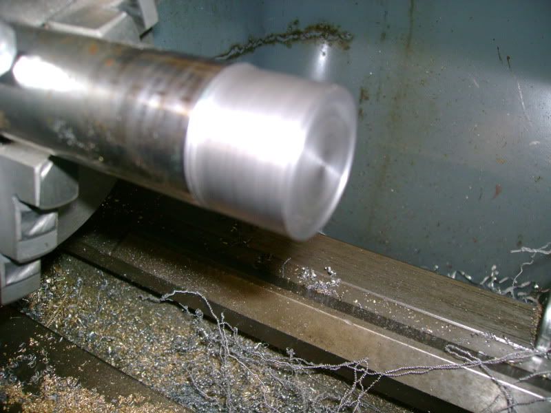
Plain diameter turned, note compound slide now set over for taper cut.


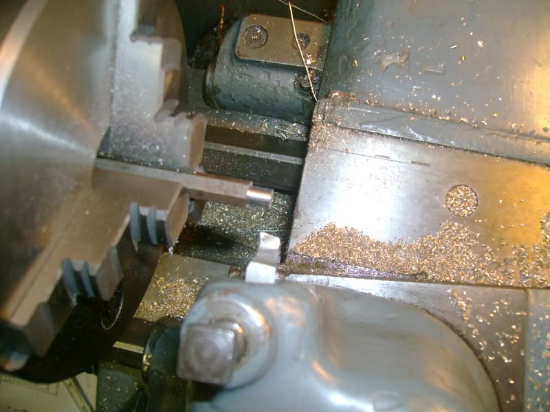
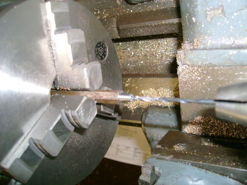
Taper cut, drilling hole through.


Not a very good shot but it’s supposed to be of the tool I ground to cut the grooves  - Is this called a barb? I ground the tool to 50 thou thick with a  21 deg angle on the end – this was guessed – it’s not really critical. There are 5 grooves / flanks whatever you want to call them over the 1/4 “ nozzle.


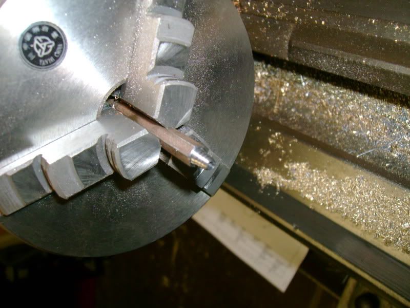
The nozzle end finished.


Quite pleased with how that went I was admiring it when I suddenly thought, how the hell am I going to turn the plain dia and cut the thread on the other end now, since I only have 3/16” hex left to grip – and I would be machining right up to the chuck at that.


If I had done it the other way around, I could have tapped a bit of rod and screwed it into that to cut the nozzle end, but this way I had no chance. Unless, I used the ER collet chuck from milling machine – so this was the plan. I would grip the very small parallel section on the nozzle end and take light cuts to get the thread dia down to size then cut the thread with a die.
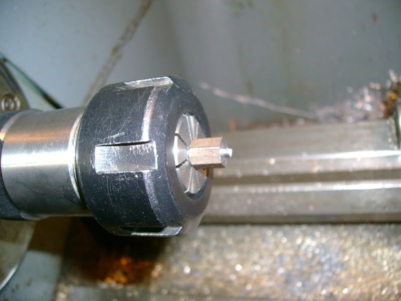

It fell out once, hadn’t tightened the chuck enough,  but luckily there was no damage and it lived to have another go. I put a drill down the middle so it wouldn’t crush anything and nipped it up pretty tight.  It worked. I used the small grooving tool to make a thread undercut.


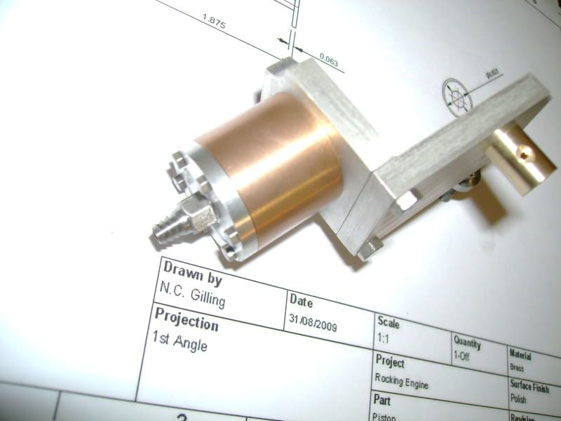
Inlet nozzle added to assembly.


At this point I thought I’d cut my losses and just started to gather the materials together for the remaining components.

The wood is for the piston, brass hex for the flywheel  and large dia steel bar to give it a nice sturdy base. Not really, just checking you’re still awake! :lol:
Unfortunately I couldn’t find any round brass for the piston, the only suitable brass I have is the 3/4 “ hex, so it’ll have to be made from that. Seems a shame but it’s not really wasting it is it.
Stew, you might recognise the steel for the flywheel, it’s an old proof shot nose! If I recall correctly I’ve machined this before and it’s pretty tough but not that bad. Not looking forward to sawing it though!
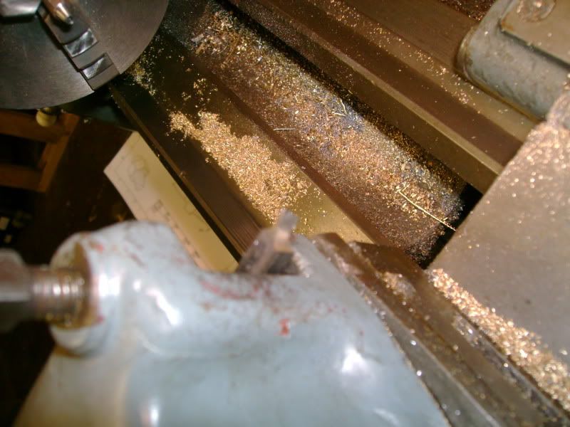
I couldn’t find any steel round bar big enough for the crankshaft either, until I looked in another box under the bench and remembered I had a large length of what I think is some sort of chromium steel? Just to prove I use  a hacksaw:

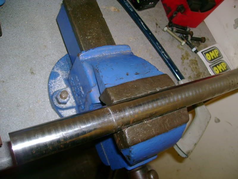
Not much fun but I timed it and it took exactly 5 mins to get through this 1 ¼ “ bar.

Stuck it in the lathe and did a quick machining test. Took a few facing cuts across. Left a good finish and didn’t seem too hard. Then turned down  a bit, this didn’t give such a good finish but this was at about 300 rpm. Gave the tool  a rub with water of air stone and it gave a much better finish, so I think I’ll just need nice and sharp tooling for the finishing cuts. I think it’ll take a while to whittle this down to size though.

On the diameter it gave a bit of a weird finish, it was fine, but sort of a bit rough to touch. Like very very fine sand paper. Almost as if it’s left microscopic tears all over the surface. I wonder if my rake angle is too high and it would prefer a shallower one like brass? Never the less, all it would need from there was a very slight rub with emery cloth to make it nice and shiny.

Bit more pleased with my progress now, there’s still a bit to do but at least I have a bit to show for it now.
There are a couple of straigh forward components and a couple of critical ones but they are straight forward really. Apart from the crank, I remember what a pain it was to set off centre in the 4 jaw last time. This time I might try to make a split collet and do it in the 3 jaw.
Still to do :-

2 Off pedestals
Wooden Base
Crankshaft
Flywheel
Piston / rod / big end combo

So, that’s only 3 more bits to see if it’ll run – 2 more if I rob a flyhweel off something else! No, that’s cheating. I might even make the base and pedestals first so it stands up by itself!

Thanks very much for following and for all your comments / advice.

Nick

Ps. hope you are enjoying this as much as I am. If you have any suggestions about how I should write the thing up please let me know. I do tend to waffle a lot and I’m not sure some of this is worth putting in, there’s a lot of straight forward turing / milling.

Location: County Durham (North East England)

bogstandard

  • Guest
Re: Modified Rocking Engine
« Reply #37 on: September 11, 2009, 10:40:40 PM »
Thats a lot better Nick, you are not out of breath any more, just a slight wheeze.

Nice write up and description.

I will just add a bit about barbs on inlets.

I use silicone fuel tubing for my air transfer, and if you do the same, you should not have any sharp edges on your inlet spigot. If silicone is 'nicked' it will split and tear straight away. I use undulations on my spigots, filed on and shaped by hand, with nice rounded edges.

Bogs


Offline sbwhart

  • Global Moderator
  • Hero Member
  • *****
  • Posts: 3530
  • Country: gb
  • Smile, Be Happy, Have Fun and Rock Until you Drop
Re: Modified Rocking Engine
« Reply #38 on: September 12, 2009, 01:38:23 AM »
Going well Nick write up is just fine  :thumbup: keep em coming.

Have fun

Stew

PS Yes I did recognize that bit

Stew
A little bit of clearance never got in the road
 :wave:

Location:- Crewe Cheshire

Offline raynerd

  • Madmodder Committee
  • Hero Member
  • *****
  • Posts: 2893
  • Country: gb
    • Raynerds Projects - Raynerd.co.uk
Re: Modified Rocking Engine
« Reply #39 on: September 12, 2009, 01:59:34 AM »
Hi Nick -  coming on nicely!  :clap:

 
Chris

Offline arnoldb

  • Hero Member
  • *****
  • Posts: 515
  • Country: na
  • Windhoek, Namibia
Re: Modified Rocking Engine
« Reply #40 on: September 12, 2009, 04:29:36 AM »
Good going Nick

I like your write-up - good couple of bits in there put a smile on my dial  :thumbup:

Cheers, Arnold

Offline NickG

  • Madmodder Committee
  • Hero Member
  • *****
  • Posts: 1890
Re: Modified Rocking Engine
« Reply #41 on: September 12, 2009, 01:38:38 PM »
Cheers guys, thanks for the support.

Bogs, I usually use the soft fuel type tubing too, didn't think of it tearing, I was trying to make it so it wouldn't come off. May need to round those off with a file. I think i've made the taper too steep anyway to be honest.

Well I should be telling you about what bit I made today. Originally, I was going to get some time in the workshop today during the day, the wife and kids were supposed to be going to meet up with the mother in law on their own. But this morning she started moaning and asking me to go too, I wasn't going to but thought that would come back to bite me, so I did! I was supposed to get a bit of 'shop time' when we returned but we decided that seeing as it was such nice weather, we'd have a bbq. This meant I was in the workshop but was fixing the bbq! :bang: It's very fragile cast iron and my son kept knockin it over in the old house. He'd snapped one of the brackets off for the thing you rest the grill on. So I had to cut a bit off that, drill and tap 1BA and add a little bracket of my own. I found a bit with 2 holes drilled in the right place from an old project and even a csk screw with it! Just shows never to chuck stuff out! :lol: I think this material was ali bronze, the colour is sort of, well, somewhere between aluminium and bronze, like a very pale shade of brass. Will take a pic later.

I think I might even give the crankshaft a go later. I just remembered I have some steel much nearer the size, so getting a sweat on cutting that 1 1/4" chromium steel could have been for nothing! Although this other stuff has previously been forged so it might be a bit tough ... when it's machined on the cnc's at work it squeels like mad! :dremel:

Hopefully will update you all later.

NIck


Location: County Durham (North East England)

Offline NickG

  • Madmodder Committee
  • Hero Member
  • *****
  • Posts: 1890
Re: Modified Rocking Engine
« Reply #42 on: September 14, 2009, 02:29:11 PM »
Right,

Back onto this ... i've missed two nights installations as had a bit of a nightmare over the last couple of days, well not as such, just things didn't really go to plan.

It seems there's been a hive of activity on the forum, I almost couldn't find my thread after replying to all the new / updated stuff! Looks like it's going well. I think Bogs thread a couple of months ago really kicked things into life.

On Sat night I started on the crankshaft. Didn't get in the garage until 10pm, and didn't get out until 2am - hence no write up!

The crankshaft didn't really pose too many problems, just took a lot longer than I thought. There was a lot of material to remove.
Luckily I found this whacking great tool that was probably sharpened by my grandad god knows how many years ago. But because of that, it worked well!


The swarf was a bit scary though, didn't really like this task.


The thing started to shape up, I was taking pretty large cuts, probably around 1/8" at first but ended up taking 10 and 5 thou cuts as the diameter reduced.


I thought I'd left it a couple of thou oversize but did a test fit in the bearing, at which point it slid merrily in. Probably marginally looser fit than I would have liked but once it's got a film of oil in there it's good, I want as little friction as possible really. As long as the flywheel doesn't wobble and I don't think it will. I later found out (when making a different component) that the problem was my cheap digi verniers. There is some error between the internal measuring bit and the external. I should use the starret ones my grandad gave me, they'll be a damn sight more accurate, just so fiddley to use and hard to see. Maybe I need to get another pair of digi ones as they are so convenient.


Anyway, marginally happy with that so part off a couple of thou over, I like taking a facing cut after to ensure better finish, get to spot on length and to get rid of the pip.


Found a bit of aluminium for the split bush...I said I'd do it this way instead of messing around with the 4 jaw. I'm not experienced enough with that yet and it would have taken me hours.

Face to length


Mark where to drill hole:


I missed the pic of drilling but did it in the mill with a V block to keep it vertical.

More trusty hacksawing, I didn't go right through, just left a couple of mm holding it together - glad I did that or it would have been fiddley.


Crankshaft was a nice tight fit in bush:


In the lathe ready for the offset turning.


Note different cutting tool below, I managed to mess up that big one by trying to sharpen it! Don't know what it was but I put a steeper rake angle on it ... normaly about 20 deg for steel, where as before it was pretty flat. The tool below is the one I use for brass so only a couple of degrees rake angle, this forged steel likes that for some reason, maybe more rigid?


Finished crankshaft. It just took ages, I didn't like turning along the spindle axis so I did it by taking facing cuts across the piece until it left a pin of about 3/16" dia, then took the pin down to size. It still took a long time but there wasn't all that chatter etc.


Pretty pleased with it, although I can see that part of the disc is thicker, it won't affect performance as it's on the back face, not sure why though, must have got the hole in the bush wonky somehow. I did the same thing on my hot air engine and that was straight in the 4 jaw though ... not sure why!

Assembled with rest of engine:


I'll post last nights component as another reply as this may crash!

NIck


Location: County Durham (North East England)

Offline raynerd

  • Madmodder Committee
  • Hero Member
  • *****
  • Posts: 2893
  • Country: gb
    • Raynerds Projects - Raynerd.co.uk
Re: Modified Rocking Engine
« Reply #43 on: September 14, 2009, 02:49:57 PM »
I can`t wait to see this one running, it is looking great!!

Chris

Offline NickG

  • Madmodder Committee
  • Hero Member
  • *****
  • Posts: 1890
Re: Modified Rocking Engine
« Reply #44 on: September 14, 2009, 02:51:13 PM »
 :jaw:


Brass turning nicely with that same tool as the crank! Took a big enough cut to get past the hex bit ... no problem.


Lot of material to come off here too ... had to double the longitudinal feed speed otherwise I'd still have been there! I must be getting lazy, don't like turning the handwheel now!


All going pretty well, couple of finishing cuts on the rod.


The middle was to be wasted down further still.


Started parting off, then filed the radius in situe. A test fit on the cylinder resulted in lots of swearing as it was already quite a bit undersize ... good rattling fit which wouldn't have worked. I put this down to getting different measurements between the internal and external jaws of my digi caliper .. piece of cheap cr@p! 'Buy cheap, buy twice' as someone always said to me at work ... not always the case, but in this case buy cheap, make twice, buy twice!  :lol: actually, don't know whether to  :lol: or  :( !

So:


No, I didn't do that in my temper, although I felt like it  :bang: ! I had a cunning plan, it was a good job I stopped there, I could turn that down to rod size and part off a bit further along then cut a thread on the end, make a disc from the remaining bit, tap it to suit and screw em together. By this time it was about 11:45 ... again, hence no post last night!

Disc drilled & tapped, parting off.


Rod in collet chuck again ready to turn down and thread end.


Disc screwed on, faced to length and profiled with needle file. This time checking fit in cylinder. It's still not spot on though, very easy to go a tincy bit too far with the file.


Missed the step of drilling the hole in, the pin was quite a tight fit in the big end but waggled it about a bit with some oil and it's loosened off. Still might be a tad tight, no it should be ok, spins quite freely.


The good news is, when I blow into the cylinder it gives a decent power stroke, but on the exaust stroke I can feel a bit of a power stroke too if you know what I mean. I mentioned this before, it was my fear that the piston doesn't rock sufficiently to vent the air pressure.  I have a 4" dia cast flywheel which just happens to have the right bore, so I tried that ... i could get it to turn over a few times on lung power until I ran out of puff. So, I think it will run, at certain pressures, but I think it's a marginal design. I might have to experiment a bit with the flywheel, the one I've designed might not have the inertia required to counter act pressure forces on the piston. Also, the best configuration to run these in is probably vertically with the power stroke upwards. Then you also have gravity helping on the exhaust stroke.

Will have to see.

I want to do the 2 pedestals next then the wooden base, so when I've done the flywheel it is properly finished and ready to run! This should, all being well, be Sunday night. I'm away in South wales for the next couple of days so the plan is Thurs night: Pedestals Fri Night: Base, Sat & Sun night, Flywheel, Polish, Assemble, Run!

Nick
Location: County Durham (North East England)

bogstandard

  • Guest
Re: Modified Rocking Engine
« Reply #45 on: September 14, 2009, 03:24:52 PM »
Nick,

You will get that back pressure on the return stroke because of it not having any valving.
It is the flywheels' job with the stored energy from the power stroke to overcome that reduced return pressure, and so keeping the engine running. It is a fine balance, but I don't think you will have any worries on that score, as long as there is a differential pressure.


Bogs

Offline sbwhart

  • Global Moderator
  • Hero Member
  • *****
  • Posts: 3530
  • Country: gb
  • Smile, Be Happy, Have Fun and Rock Until you Drop
Re: Modified Rocking Engine
« Reply #46 on: September 14, 2009, 03:46:34 PM »
This will be a runner Nick even if its upside down these little engines seem to be sensitive to orientation.

Could you post a pic of it up against a ruler to give us some idea of size.

Cheers

Stew
A little bit of clearance never got in the road
 :wave:

Location:- Crewe Cheshire

Offline arnoldb

  • Hero Member
  • *****
  • Posts: 515
  • Country: na
  • Windhoek, Namibia
Re: Modified Rocking Engine
« Reply #47 on: September 14, 2009, 03:55:42 PM »
Looking good Nick  :thumbup:

I've not yet gotten my "baby" compared to your's rocker to run on breath power - flywheel's a tad too heavy.  But after a couple of demonstrations to friends it seems more and more eager to do that; maybe just some run-in required, you could have a similar problem  :scratch:.

Enjoying your thread :) might just have another case of  :proj: coming up  :lol:

Cheers, Arnold

Offline NickG

  • Madmodder Committee
  • Hero Member
  • *****
  • Posts: 1890
Re: Modified Rocking Engine
« Reply #48 on: September 14, 2009, 04:51:24 PM »
Bogs, good point, and I dare say there is more differential pressure than in a stirling engine of the same size so it should run.

Stew, will take a pic with a ruler, I always forget to put something in for scale. I know some people use coins, that is a good idea, will starting doing that ... if I can find any!

Arnold, I think it will get better with run in, as I haven't lapped the bore it's probably not as good as it should be so a bit of wear should help. If it doesn't run, then I'll pay more attention to that, it's pretty smooth anyway. I specifically designed it with quite a large bore to make it run on low pressure. So on mine the pressure isn't a problem, it's just the volume of air required to keep it going ... especially as on the rocking engine you lose a lot on the exhaust stroke!

So you should have :proj:!!! Most people have made one of these rocking engines now, if you don't you'll be the odd one out  :lol: So go on ... get started!!!!

Nick

ps The start of my last post was meant to say, the pics were taken with the new camera I wen't halves with the wife on ... so please say they are far superior to the old just to make me feel better! £165 that cost me!!!

 
Location: County Durham (North East England)

Offline arnoldb

  • Hero Member
  • *****
  • Posts: 515
  • Country: na
  • Windhoek, Namibia
Re: Modified Rocking Engine
« Reply #49 on: September 14, 2009, 05:44:23 PM »
 :lol: :lol: Nick, Have done here :lol: :lol:
But I'm due for another secondary infection  :doh: have to finish one for my one sister before mid October for her birthday; she just said "I want one" - and that sorted out the b-day gift  :lol:

Cheers!