Here is a pictorial description of a project that was easier in concept than achieving it. Essentially I wanted to vector the measurement of the Lathe Compound movment to the X and Y axis.
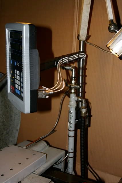
Explanation: The Newall C-80 has a Vectoring feature in which, after the angle of the Compound is entered, the movement is apportioned to the appropriate axis. If the angle is, say 0° then all the movement is added to the Y axis while if it is entered as 90° then all the movement is added to the X axis readout. Of course angles in between are added to each scale proportionally so a 45° setting would increase the X axis the same as it would increase the Y axis.
Why bother? Well there are several benefits to this if, for example, the Compound is parallel to the work the finer motion of the Compound can be used for greater accuracy and the displacement is automatically added to the X axis. If the Compound is set at 88° for every inch the Compound is moved forward it will only move .035" towards the work piece. It is obvious that more accurate positioning is possible. It is also a handy feature when cutting angled faces.
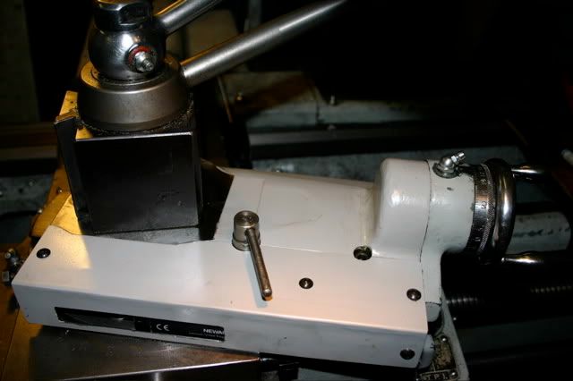
First the top was refaced to make room for an Aloris Tool Post
After much grief because of tight restrictions the scale was somewhat incorporated within the Compound to minimize dangling cables.
The Compound Base Plate was added to, milled, and drilled to pass the cables through it.
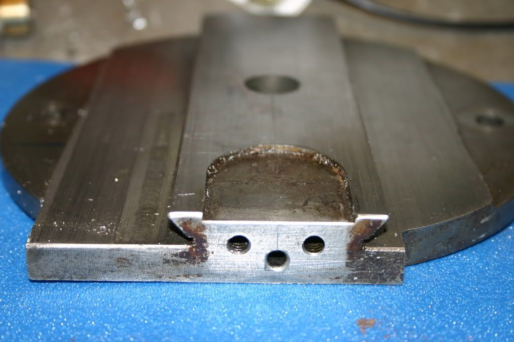
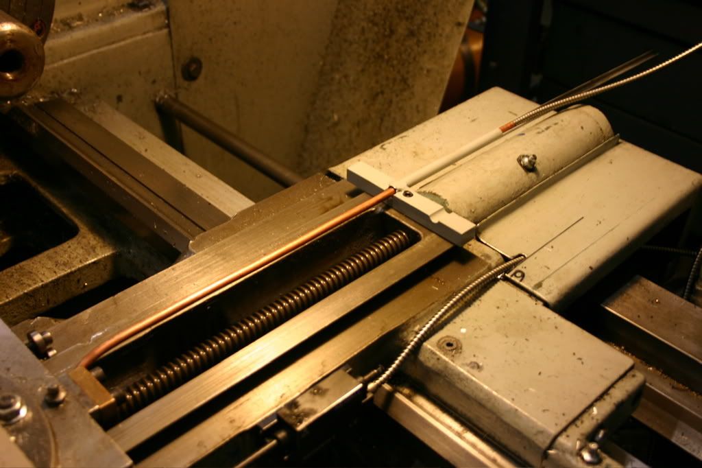
The cable goes down the center hole into the copper tubbing to keep it away from the Cross-Slide.
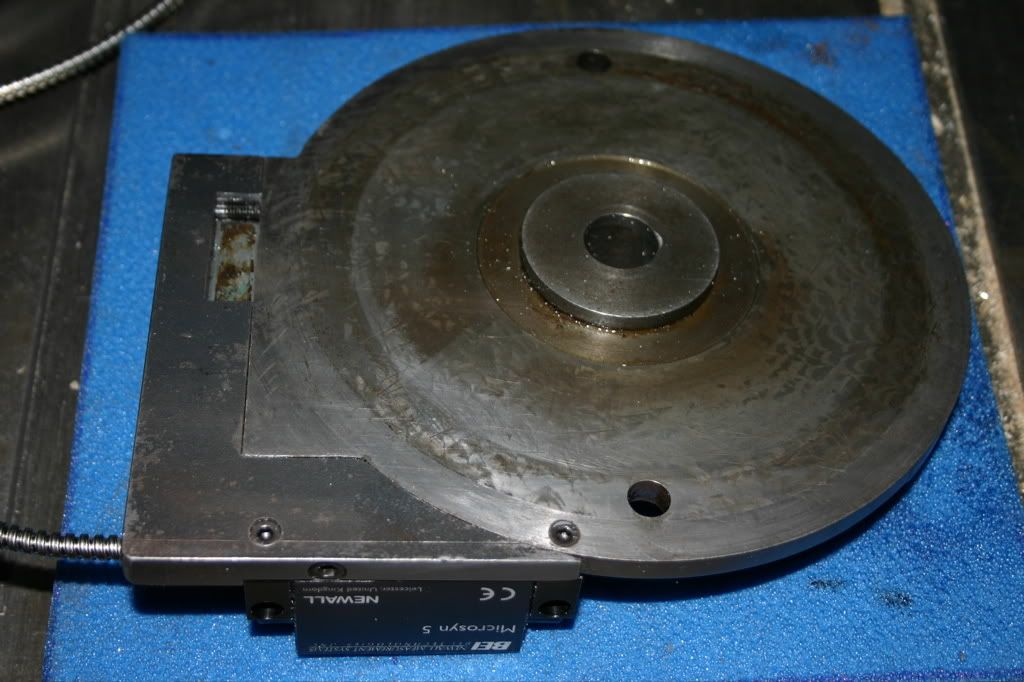
This is what it looks like without the Cover Plate. Unfortunately none of the supplied scale hardware worked for me.
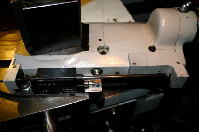
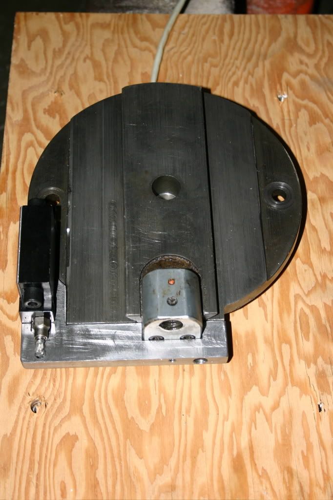
The covered version looks like this. The slot is for access to the Clamping Nut and the Oil Zerk
The Read Out moves with the Carriage therefore the cables were shortened to clean up the installation.
Raymond


