Author Topic: a nine cylinder radial engine, plans by "ageless engines"  (Read 102975 times)

Offline madjackghengis

  • Hero Member
  • *****
  • Posts: 717
  • big engine
Re: a nine cylinder radial engine, plans by "ageless engines"
« Reply #100 on: May 02, 2010, 11:47:42 AM »
Well all, that nice steel blank which looks so good on the rag balled up a lump inside the hole when I went to press a shaft in it, so hot rolled steel is not an option, no matter how pretty it looks before the work.  I've been cogitating on this problem, once the holes for the main shafts and for the crank pin as well as the alignment pin are drilled, bored and reamed, trying to use a carbide face mill to reduce the thickness of the web of the crank means interupted cuts, which have no relationship with flat.  After long thinking, I decided to get back to the already hardened steel and try again, another way.

these are the two new blanks I will be machining to try to get a crank that is straight.

using the shaper to clean one face of the one blank

and working on the other blank.  After cutting both sides of both blanks, I found two to three thousandths from parallel between the two sides of both blanks.  After checking everything else, I checked my parallels I was using, and it turns out I was using a set which are not parallels at all, but just mostly the same size.  Going through my blank tool bit drawer, I found two half inch tool bits which miked out to exactly five hundred, and put both blanks back in the shaper and did a three thousandths finish cut on both sides of both blanks, ending up with the sides parallel within about a thousandth, I think I can work with this, and work out the difference as I shape them to their final dimensions.

This is one of the blanks on a tool maker's flat, with four cigarette papers to test flatness, one paper is a bit loose, but still sticks, the other three feel pretty much equal.  The second blank finished up pretty much the same.  I'm caught between machining the cheeks down to their proper thickness at the crank pin, and then drilling, reaming, and boring as appropriate, or doing the cheek thinning first, and then reaming and boring the respective holes.  Since both the main shaft holes, bored, and the crank pin holes, reamed, are in the thinned section, and their presence contributed to the interuption of the cut, leading to not flat surfaces, I think I will try thinning first, and then putting in the respective holes.  Having made three sets of cheeks, I have decided its the long haul, and if they don't work out I've got plenty more old steel, for the next set of blanks to be cut from.  I will produce a straight well mannered crank shaft that fits the bearings, and rotates moving all the rods, no matter how many blanks it takes.  I have taken great liberties with the design of the crankshaft, as I don't like the original design, and none of my experiences does anything but further solidify my belief the original design is lacking in both strength and stability. I am ready to have a straight working crank today, if it is at all possible, however I've got a couple more ideas if these don't produce it.  Thanks for all the comments and support, makes me feel like I'm in a modelling club, something I've always wished for but was never around.  Lots of inspiration for good quality work. :mmr: :beer: mad jack

Offline Bernd

  • Madmodder Committee
  • Hero Member
  • *****
  • Posts: 3688
  • Country: us
  • 1915 C Cab
    • Kingstone Model Works
Re: a nine cylinder radial engine, plans by "ageless engines"
« Reply #101 on: May 02, 2010, 05:54:06 PM »
Pretty presistent you are there Mad Jack.  :clap:

Before long you'll be able to say' "I now know how not to produce bad crank cheecks." (Think fo Thomas Edsion when asked about his light buld. He said he knew 101 ways how not to make them)

Hang in there I'm sure you'll get a pair soon.  :thumbup:

Bernd
Route of the Black Diamonds

Offline kvom

  • Hero Member
  • *****
  • Posts: 520
Re: a nine cylinder radial engine, plans by "ageless engines"
« Reply #102 on: May 02, 2010, 07:15:09 PM »
I think milling before drilling will be superior, as milling can relieve some stress in the metal and cause the holes to move.

Offline madjackghengis

  • Hero Member
  • *****
  • Posts: 717
  • big engine
Re: a nine cylinder radial engine, plans by "ageless engines"
« Reply #103 on: May 03, 2010, 10:12:51 AM »
Hi all, Kvom, that is essentially what I concluded, and yesterday, machined the blanks so that all that is left is the reaming of two sets of holes, and the boring of the mainshaft holes, since I don't have that odd sized reamer.  I don't know what kind of steel this is, though I suspect it is something like 1045 or the like, but it must be around C40 or better rockwell by the way it machines.  The hot rolled I tried was easy to get to dimension and form, but didn't even take a light press fit without damage to the bore, and the crank has to be assembled serveral times to put this engine together.  I have a few more ideas if today doesn't make things happy, I only know plenty of people have built this engine before me, and been successful, and therefore I will be.  I will take scrap and weld it together to make a crank if that's what it takes.  I took some pictures yesterday, getting the cheek blanks ready, and will take more today, as I make holes and cut out the profiles and see how things go together.  Till then,  :mmr: :bang: mad jack

Offline madjackghengis

  • Hero Member
  • *****
  • Posts: 717
  • big engine
Re: a nine cylinder radial engine, plans by "ageless engines"
« Reply #104 on: May 07, 2010, 11:23:28 AM »
having machined the step in the crank cheek blanks in the shaper, and matched them as close as possible, I put them in the mill vise and drilled and reamed the crank pin hole and the alignment hole, and bore the main shaft holes, as they are not a standard size.


with all the holes done, I profiled the blanks by scribing the outline of one of the old ones on both blanks, and cut them out with the bandsaw, then used a belt sander to get them close, and a file to finish them as matching, and to the line.
here's my tangential radius profiling attachment for my work bench, set up to finish off the radius around the crank pin end

another view of the profiling attachment

with the cheeks on a mandrel, machining the radius on the counter weight end on the lathe


the new cheeks, ready for deburring, with an old cheek showing the un-even surface of the interior which caused the problems with getting the crankshaft straight.  An example of cutting hardened steel with a multi-insert face mill and interupted cuts causing mountains and chasms.
another shot of the cheeks on a mandrel, machining the radius.


I turned the ends of the existing crank pin down to match the reamed holes, assembled the crank, fitted it in the case, found it was too wide, took fifteen thousandths off each end of the crank pin shoulder in a four jaw chuck, pressed the crank back together and found it now fit, with about ten thousandths end play, probably should have measured before machining.


I think a new crank pin is in order, this time with real, actual numbers to work with.  I've got a piece of stock missing in the shop, and its what the crank pin and shafts were supposed to be made of, but I can't find it.  When I do, I will make a new crank pin, and a new front prop shaft, as the one I just made seems to have a slight bend in it.  I think the unknown steel I used because it was heat treated is still soft in the core explaining two bent prop shafts which have appeared when they were straight the night before.  Have to find that heat treated 4140 stock and finish the crank, so I can move on to more interesting things, such as the master rod and the oil pumps.

Offline sbwhart

  • Global Moderator
  • Hero Member
  • *****
  • Posts: 3530
  • Country: gb
  • Smile, Be Happy, Have Fun and Rock Until you Drop
Re: a nine cylinder radial engine, plans by "ageless engines"
« Reply #105 on: May 07, 2010, 11:44:03 AM »
Great work with the crank Jack  :clap:

When you see the assembly of the crank case it sure looks impressive.

Cheers

Stew
A little bit of clearance never got in the road
 :wave:

Location:- Crewe Cheshire

Offline madjackghengis

  • Hero Member
  • *****
  • Posts: 717
  • big engine
Re: a nine cylinder radial engine, plans by "ageless engines"
« Reply #106 on: May 09, 2010, 10:27:10 AM »
Thanks Stew, I feel like part of a model engineering club.  I've been happier in my "projects" in the last few months than ever before, it's nice to see other's work and to have your own work viewed, commented on, and suggestions made when walls are hit.  I have a feeling I'm going to get some things I've put off for a long time, done, because of the extra motivation and the interest watching all the other projects brings out in me.  I'm really looking forward to the starting on the connecting rods, starting with the master rod. :nrocks: mad jack

Offline cedge

  • Madmodder Committee
  • Sr. Member
  • *****
  • Posts: 327
Re: a nine cylinder radial engine, plans by "ageless engines"
« Reply #107 on: May 09, 2010, 09:10:39 PM »
Jack...
Having seen one of these up close and personal, I'm in awe of the complexity of the project and the fit and finish you're bringing to it. For all the kind words you've spilled on me of late.... all I can say is.... "Back Atcha Dude". Incredible work!!

Steve

Offline madjackghengis

  • Hero Member
  • *****
  • Posts: 717
  • big engine
Re: a nine cylinder radial engine, plans by "ageless engines"
« Reply #108 on: May 11, 2010, 12:31:11 PM »
And thank you for the complement, Steve, much appreciated.  The crankshaft had to be disassembled for more work, and I found the front shaft bent again, so a new one was made out of completely different material, and looks to be the last one for this engine, hopefully.

Along side, you can see the last four front shafts, only two of which ever got in the crank.

Another shot of the crankshaft and bad shafts

At this point, I'm ready to see about the master rod, so I can assemble the crank shaft for its last time and be done with it.  Once it is in place, I should not have to take the crank apart unless I have a catastrophic failure.  We kind of hope that won't happen.  While the drawing is pretty clear, I suspect I will only be using it as a guide, and will make modifications along the way, as all the other parts have experienced.  Tally Ho, and on with the project, as Cedge said, a minute or eight hours, it doesn't matter, it's being in the shop.  or something like that.  I came home last night with a crankshaft in the case that barely turned, and having turned it by hand all evening, it spins over very nicely and should do well with pressure oil fed to it.  ta ta for now, mad jack

Offline madjackghengis

  • Hero Member
  • *****
  • Posts: 717
  • big engine
Re: a nine cylinder radial engine, plans by "ageless engines"
« Reply #109 on: May 12, 2010, 12:37:05 PM »
Well, I started on the master rod yesterday, it calls for a chunk of 6061 .750 thick, three and three quarters long, and an inch and five eighths wide.  I have half inch, and one inch, but no three quarter, so a chunk of "jig plate" aluminum plate which has been surface ground on both sides, was found in the cut off pile, being nothing like rectangular, I cut out a piece big enough, laid some lines on it, and milled two sides parallel, and both ends perpendicular, and then put it on parallels to drill and ream the crank pin location, and the wrist pin hole.  Then I started flycutting the first side to thin it down to three quarters

to keep the sides parallel, I cut about forty thousandths at a time, taking an eighth off the first side.

second cut

last cut on first side

first cut on second side

getting close

miking the blank for the final cut

Having drilled and reamed a quarter inch hole to locate the crankpin hole, and drilled and reamed the wrist pin hole, time for the four jaw

After using a quarter inch pin in the tailstock chuck to get the blank pretty much in place, the last few thousandths of centering is done with an indicator

another shot at the centering, and the end of the day

maybe the crank will be a one time proposition, it'd be nice, at least the blank is on size, and in place.

Offline madjackghengis

  • Hero Member
  • *****
  • Posts: 717
  • big engine
Re: a nine cylinder radial engine, plans by "ageless engines"
« Reply #110 on: May 16, 2010, 11:26:25 AM »
With the master rod blank in the four jaw, starting to machine it down to size

both sides will be machined down leaving the "big end" thick, for the slave rods, and bringing the master rod down to 5/16ths thickness

after leaving a shoulder for the bushing, and an inch and a half big end, the rod is flipped in the four jaw, re-centered, and the second side begun

With both sides faced off, the master rod is ready for cutting out the rod for the #1 cylinder, and machining off the excess around the big end

With a 5/16ths button in for the wrist pin hole, lines for the sides of the rod are scribed with a 3/8ths hole reamed on either side to locate the bottom of the taper of the rod sides.

after scribing the lines, it is set up on the rotary table and centered for machining off the excess

light cuts and careful operation are the key to not letting a cutter grab the part and take a bigger bite than you intend, when it is almost done, I removed it, cut the rough lines of the "rod", reinstalled it on the rotary table to finish the radius on each side of the "rod", as it connects with the big end, the sides are also milled out straight with the slight taper in the rod.

this shows the main operation of reducing the big end to round, lots of swarf flying

the master rod, ready for the sides to be milled and the recess in the big end, milled to allow the slave rods to fit to the master.  The rod is set up on the rotary table, an arbor has been made to hold a 3/16ths cutter which will be used to mill the recess around the big end of the rod.  This is how I left it last night, and today will see how the milling goes.  With a bit of luck, I will be working on slave rods next.  mad jack

Offline Stilldrillin

  • Global Moderator
  • Hero Member
  • *****
  • Posts: 4972
  • Country: gb
  • Staveley, Derbyshire. England.
Re: a nine cylinder radial engine, plans by "ageless engines"
« Reply #111 on: May 16, 2010, 12:15:51 PM »
Blummin good work well shown, Jack!  :clap:

I`m just following, and appreciating what you`re doing, quietly.....  :thumbup:

David D
David.

Still drilling holes... Sometimes, in the right place!

Still modifying bits of metal... Occasionally, making an improvement!

Offline sbwhart

  • Global Moderator
  • Hero Member
  • *****
  • Posts: 3530
  • Country: gb
  • Smile, Be Happy, Have Fun and Rock Until you Drop
Re: a nine cylinder radial engine, plans by "ageless engines"
« Reply #112 on: May 16, 2010, 12:27:56 PM »
Blummin good work well shown, Jack!  :clap:

I`m just following, and appreciating what you`re doing, quietly.....  :thumbup:

David D

Me too

Great job

Stew
A little bit of clearance never got in the road
 :wave:

Location:- Crewe Cheshire

Offline shoey51

  • Full Member
  • ***
  • Posts: 214
Re: a nine cylinder radial engine, plans by "ageless engines"
« Reply #113 on: May 16, 2010, 06:13:34 PM »
Blummin good work well shown, Jack!  :clap:

I`m just following, and appreciating what you`re doing, quietly.....  :thumbup:

David D

Me too

Great job

Stew
Me three
great work :thumbup:

Offline madjackghengis

  • Hero Member
  • *****
  • Posts: 717
  • big engine
Re: a nine cylinder radial engine, plans by "ageless engines"
« Reply #114 on: May 17, 2010, 10:02:53 AM »
You'all better watch all those complements, might make my head swell, and I might not make it through the door!  Thanks for looking and the comments, it feels like a club or pretty close.  In finishing out the master rod, I started out centering the rod on the rotary table, preparing to cut the slot around the big end, the space for the slave rods to fit in and get pinned in place.  I started with a 3/16ths side cutting slitting saw, centered on the width of the rod, taking .100 in passes, and stopping just short of touching the "rod shaft" on either direction

lots of swarf, not much cutting pressure or torque on the rod by the cutter

another cut, more swarf

one of the last cuts with the initial cutter, good depth, width is .010 on both top and bottom as well as depth

first cuts with the 5/16ths keyway cutter, stoned the face and the clearance angle on the cutter to give a clean finish cut, before starting the cutting

one of the final cuts, I took out the .010 on top and bottom in three cuts, two of .150 depth, the last cut being .055 taking out the last of the width, and taking out the final .010 depth.  This clears the back side of the recess for the slave rods to swivel side to side, and required touch up with a 5/16ths end mill to ensure clearance for #2 rod and #9, as they are where the final cuts meet with the straight lines of the rod meeting the "big end", and ensuring clearance using the key cutter would eat into the shank of the rod too much.  Final clearance for these two slave rods was made carving out the radius left by the end mill, with a pocket knife, leaving a flat face top and bottom for the slave rods.

with a piece of scrap in the vise, I drilled it and reamed it for the 3/16ths pin the wrist pin size, and using a pin in the hole, and the rod end over the pin, and the side of an end mill, I radiused the small end of the rod

the last step is drilling an oil hole in the small end, to oil the wrist pin when it is in place, this was done with a #1 center drill, leaving a conical center to hold oil.

the finished master rod, lying next to the crank shaft it will have to fit on.  The plans call for a bushing for the master rod to run on, I didn't have one long enough, but I did have six that were new and too short.  Since the crank pin is supposed to have a groove around it to allow lots of oil to this bushing, I chose to press in two bushings from the opposite sides, with their inside bevel end both meeting in the middle, and essentially forming an internal groove in the bushings, then reamed the bushings, and turned the ends off to final length to fit between the cheeks of the crank.  Next move is to finally drill the oil passages in the crank now that I have a master rod to test them in situ.  I don't like the design of the slave rods, so I will be modifying it a bit, to give them some character, and have them look more natural.  I have a dozen or so slave rods from a full sized Jacobson radial engine for examples.  While the master rod came out as expected, and appears to be in spec and should work, it looks like a model, and less like an original than I think it should.  If it doesn't work and fit right the first time, I will redo it, only with some different aspects so it looks more like an original has more radii where planes of it intersect for strength and greater ease in machining.  We shall see how things fit together before anything like that takes place.  I chose to machine lightening grooves in the sides of the rod, rather than in the faces, following the original rods.   :headbang:  mad jack

Offline Bernd

  • Madmodder Committee
  • Hero Member
  • *****
  • Posts: 3688
  • Country: us
  • 1915 C Cab
    • Kingstone Model Works
Re: a nine cylinder radial engine, plans by "ageless engines"
« Reply #115 on: May 17, 2010, 07:04:53 PM »
Lookin' real good Mad Jack.  :thumbup:

Looks a bit scary using that cutter and only having one bolt to hold it all down. I bet that would have made you mess your pants if that had come loose.

Oh, go back and check your math. You said you had .010 left and then took off .015 and .055. Looks like you would have been milling air. Let me guess, you got the decimal point in the wrong place.  ::)

Keep up the nice work.

Bernd
Route of the Black Diamonds

Offline madjackghengis

  • Hero Member
  • *****
  • Posts: 717
  • big engine
Re: a nine cylinder radial engine, plans by "ageless engines"
« Reply #116 on: May 18, 2010, 08:47:18 AM »
Lookin' real good Mad Jack.  :thumbup:

Looks a bit scary using that cutter and only having one bolt to hold it all down. I bet that would have made you mess your pants if that had come loose.

Oh, go back and check your math. You said you had .010 left and then took off .015 and .055. Looks like you would have been milling air. Let me guess, you got the decimal point in the wrong place.  ::)

Keep up the nice work.

Bernd
Hi Bernd, it's a lot easier keeping track of all those numbers while you're making them, then while you're trying to remember exactly what you did last night.  That last cut was a light clean up cut on three different surfaces, two parallel, and one perpendicular and round, I think I left five thousandths cut on the actual round part of the rod and fifteen top and bottom for the keyway cutter to clean up.  thanks for keeping me honest, wouldn't want this board to look like politicians like to do machine work.
With that cleared up, I looked at the master rod, and took down a slave rod from a Jacobson radial engine, looked at the rather round, slightly worked analog in the plans, and decided slave rods were boring, and I ought to finish the crank, so when it's assembled, it can stay together, so I prepared to drill the two remaining oil passages, the ones that are not parallel or perpendicular to the shafts.

master rod adjacent to the slave rod

slave rod rolled over to show profile
starting to square up the block which will become the oil passage guide

another shot of the block in the shaper

the finished block on the crankshaft, ready for use

finished block locked between pressed together crank cheeks

the holes are drilled 45 degrees to pierce the crankpin, the cheek and finally the mainshaft and main bearings

another view of the crank with the block

the top view of the crank, ready for drilling
after drilling, the crank was split to remove the guide block, this picture shows the hole leaving the crank pin, and entering the cheek of the crank

this picture shows the passage drilled to the front main bearing from the crank pin

another view of the front of the crank and the path of the oil passage
the bottom side of the front mainshaft bearing, showing the oil hole, oil seeping out of this bearing will oil the cam gears and cam, along with the front prop shaft bearing

the front mainshaft bearing with its oil hole

when the modern day drill driver didn't want to drill the oil passages, I broke out the old standby, my black and decker, had to pay a dollar at the flea market for it twenty six or seven years ago, and put a cord on it.  Most of the afternoon making the guide block, which by the way, was supposed to have a slit in it, and a clamp bolt but was avoided by making it a thousandth too long, so the cheeks of the crank held it solidly in place while drilling.  It took about twenty minutes to drill both oil passages, but I have the guide block for another engine if I were to build one.  Much more exciting afternoon than making eight boring slave rods.  Now I have to plug the ends of the oil passages in the crankshaft, to keep the oil going where its supposed to.  That will complete the crankshaft, except for final fit, and let me get on with boring slave rods and then an oil pump.  Thanks for watching, ta ta for now,  :thumbup: :headbang: mad jack

Offline madjackghengis

  • Hero Member
  • *****
  • Posts: 717
  • big engine
Re: a nine cylinder radial engine, plans by "ageless engines"
« Reply #117 on: May 18, 2010, 08:59:56 AM »
I think I missed a photo, or I tried to go too fast for a rainy day with a satalite link, here's a picture of the oil passage leaving the crank pin, and entering the rear cheek, connecting to the main oil passage from the oil pump.

I think slave rods are in order, something easy, I'm not ready to build the oil pump yet.  ta ta for now, mad jack

Offline madjackghengis

  • Hero Member
  • *****
  • Posts: 717
  • big engine
Re: a nine cylinder radial engine, plans by "ageless engines"
« Reply #118 on: May 20, 2010, 11:03:03 AM »
Yesterday was a bad day at Black Rock, clouds hung over, and fine work would not turn out well, so after wasting a couple hours hunting the right material for the slave rods, I decided to remake the front propeller shaft bearing cover.  I'd made one long ago, but in cutting it off from the thin piece of mother material, gouged it pretty good with the cut off tool.  It was on the back side, so it would barely show on the edge, but I would know what it looked like.  On top of that, I either had to take out the crankshaft and machine the bearing shoulder to center the crank in the case, or make allowance for the bearing position in the cover, and save a lot of work and possible heartbreak, if the crankshaft were to do something stupid while turning it.  I put a piece of scrap in the chuck, turned the inside profile, to match the bearing, bored the .075 depth the bearing stuck out the front cover, and flipped it, so I could put a radius on the outside, and drill and counterbore the six mounting holes.

the cover, set on the mill for drilling the hole circle for the six holes.

The cover with the holes done, counterbored, and cleaned up for mounting.

The cover, mounted on the engine's front cover

a slightly better perspective on the cover, mounted in place.
having all the crank assembled, with the master rod in place, the main bearings screwed up solid as they will be when running, I have been oiling all the bearings with teflon bearing gun oil (CLP), and spent the past two evenings spinning the crank around, using the bit of bar stock drilled, and held on with the prop nut, to work in the bearings, and loosen things up.  Each step adds a new surface that bears on something, increasing the drag, and needing working out.  It is starting to feel like an engine, and not just a shaft with a brake on it.  I can almost see light down the tunnel, only a few hundred more parts to make and it will be done.  That's all for now,  :headbang: mad jack

Offline madjackghengis

  • Hero Member
  • *****
  • Posts: 717
  • big engine
Re: a nine cylinder radial engine, plans by "ageless engines"
« Reply #119 on: May 25, 2010, 11:24:50 AM »
Lookin' real good Mad Jack.  :thumbup:

Looks a bit scary using that cutter and only having one bolt to hold it all down. I bet that would have made you mess your pants if that had come loose.

Oh, go back and check your math. You said you had .010 left and then took off .015 and .055. Looks like you would have been milling air. Let me guess, you got the decimal point in the wrong place.  ::)

Keep up the nice work.

Bernd
Hi Bernd, I ain't scared, I can do anything!!  The key to this is plenty of surface area on the bottom side of the rod on the surface or the spindle, and plenty of surface area on the top clamping area, with a snug fine thread bolt.  As near as I can tell, the master rod didn't move a bit from start to finish.  Put it down to too much seat of the pants engineering and not enough schooling.
But now I've got some progress, I've spun the crank with the master rod on it in the cases for a few nights now, got it good and loose without much slop, feels like good bearings, meanwhile, I've been getting the slave rods ready.

machining some 3/8ths plate on both sides to get it down to 5/16ths and parallel.

with the plate to thickness and squared off, I drilled and reamed holes for nine slave rods, two and an 1/8th in apart for the pins, then scribed them with lines, and cut the blanks out on the band saw

nine blanks, ready for machining to shape and size

with a pin in a drilled and reamed hole in a block in the vise, radiusing the ends of the rods by hand, very careful on the "hungry" side of that end mill

milling the rod ends, with a better perspective of the mill in the shop

a pile of slave rods with radiuses on each end

with a pin in each end, for position, milling the rods to width with an end mill, each one then flipped and the other side milled

getting ready to use a 5/32nds ball mill to slot each side .090 deep to give proper "H" profile with about .100ths web in the middle
doing the ball milling, I don't have a 3/16ths collet, so the ball mill is in a chuck, but the runout is under half a thousandth, so it works fine at 2200 rpm, even gives a nice finish

each rod is milled, burrs removed, flipped, and opposite side milled using the DRO to establish ends of slot standard

after cleaning them, each rod has an oil hole drilled in the ends with a #1 center drill

drilling oil holes in the other end

a pile of slave rods, ready for fitting

another shot of the rods

a rear view of the engine with the crank, master rod, and slave rods installed, rear main bearing removed for the photo

another perspective of the engine with the rods and crankshaft installed

looking down on the engine with crank and rods installed

a frontal view of engine with front cover, bearing cover installed, along with crankshaft and full complement of rods
Now I have to order some 2024 alloy aluminum for the pistons, it stands up to heat better than the 6000 series aluminums, and order some cast iron, or see if some of the scrap I have, can be machined for a good set of rings.  I expect to end up buying the cast iron as the quality is important if the rings are to seat in.  I think with the crank and rods out of the way, it is probably time to build the oil pumps, one to feed the main bearings and rods, and the other to scavenge all the oil out, and return it to the oil tank as this is a dry sump engine.   that's all for now, folks, thanks for looking, hope you enjoy.  mad jack :bugeye:

Offline crankshafter

  • Jr. Member
  • **
  • Posts: 59
Re: a nine cylinder radial engine, plans by "ageless engines"
« Reply #120 on: May 25, 2010, 12:45:18 PM »
Hi Jack
Only one thing to say: I'm not surprised :clap: :thumbup:

Regards
Crankshafter

Offline Bernd

  • Madmodder Committee
  • Hero Member
  • *****
  • Posts: 3688
  • Country: us
  • 1915 C Cab
    • Kingstone Model Works
Re: a nine cylinder radial engine, plans by "ageless engines"
« Reply #121 on: May 25, 2010, 04:07:23 PM »
Very nice Jack.   :ddb:

I'm impressed with your mas production work there with them rods. Nice job. :thumbup:

Bernd
Route of the Black Diamonds

Rob.Wilson

  • Guest
Re: a nine cylinder radial engine, plans by "ageless engines"
« Reply #122 on: May 25, 2010, 04:16:08 PM »
Hi M.J 

Just read through this post from the beginning  ,,,,,,,great read  :clap: :clap: :clap:  outstanding workmanship  :bow: :bow: :bow:  , one day i will grow some balls and have ago at an aero engine  :lol:

Regards Rob   

Offline madjackghengis

  • Hero Member
  • *****
  • Posts: 717
  • big engine
Re: a nine cylinder radial engine, plans by "ageless engines"
« Reply #123 on: May 29, 2010, 01:02:00 PM »
To all my friends and onlookers, sometimes work seems to insist on inserting its self into the day, and interfere with important things like model engineering.

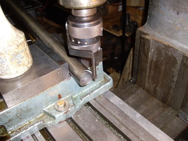
I have this frame I'm making, which needs some machine work to match up the pieces for welding, especially where the backbone meets the front main tubes, so I measured the angle, clamped the main frame tubes to a tilting table, and set up the boring head to bore at the right angle, to the size of the backbone

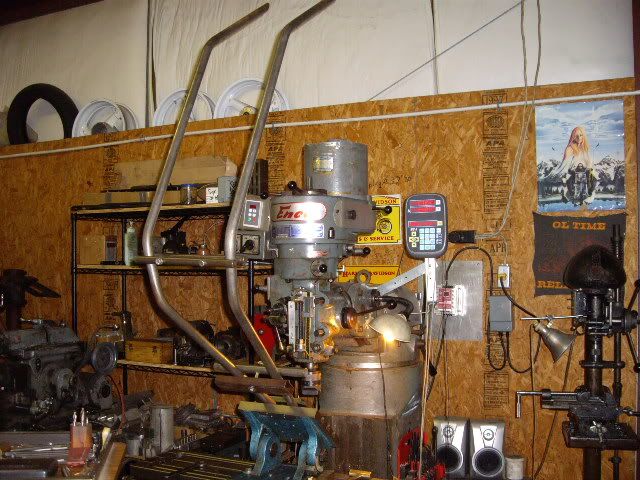
the angle plate setup with the main frame tubes clamped to it

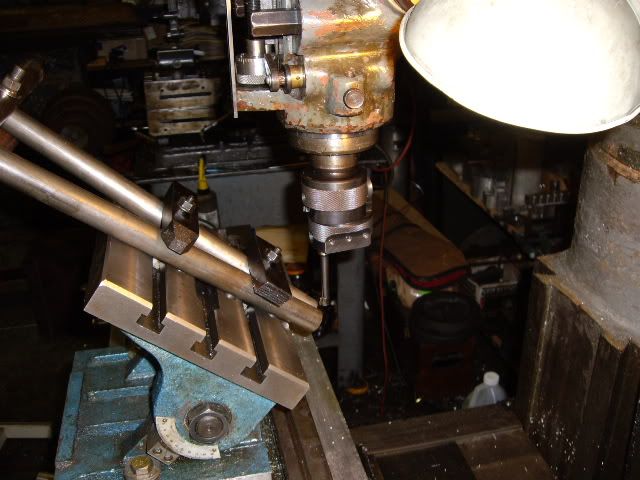
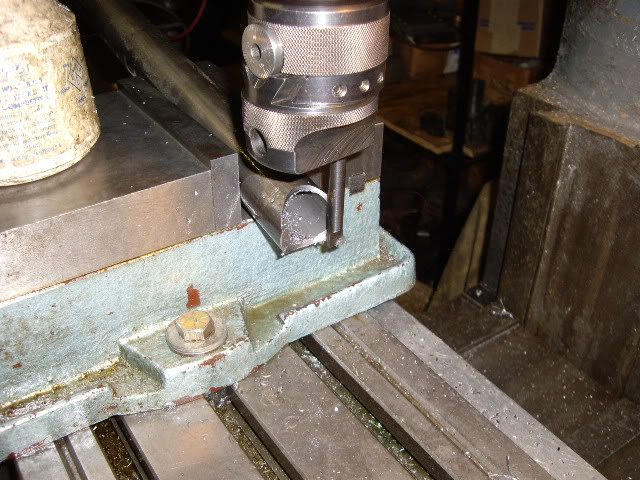
setting up the boring head.  guestimating the diameter touching off the cutter at the tube, rotating the boring head 180, and putting a rule between the touch-off point, and the cutter tip

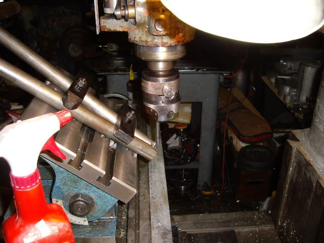
taking the first cuts and adjusting positioning for proper centering

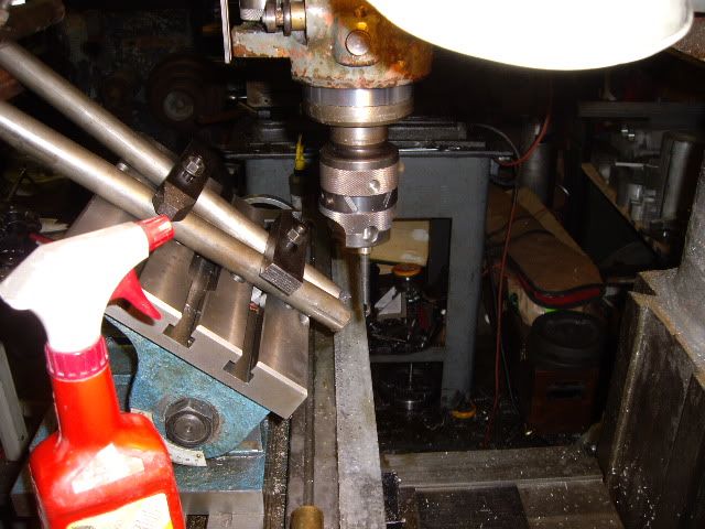
more cuts, everything in good position now.

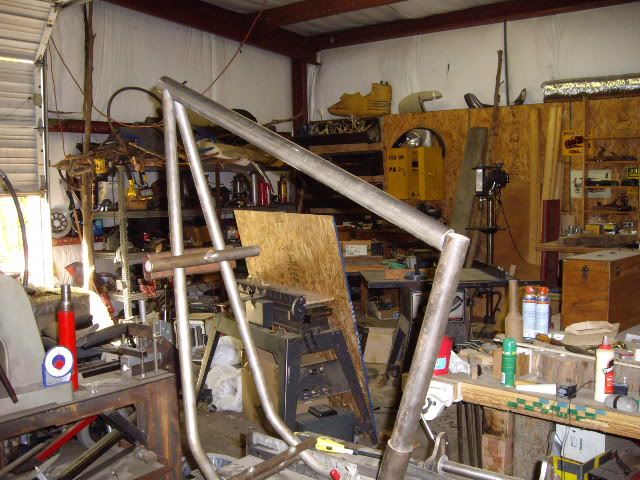
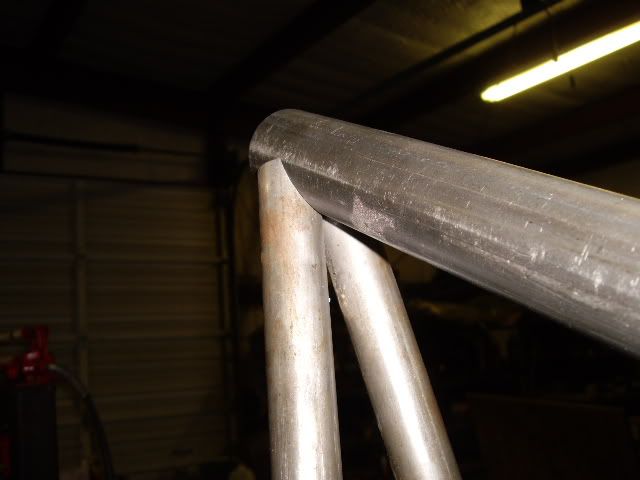
main tubes finished, testing the fit with frame in a jig

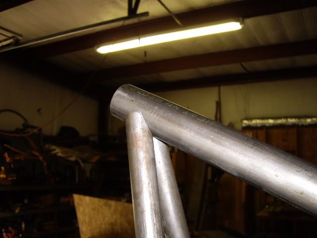
nice tight fit, no unseamly gaps, looks good

view from the front looks good too.

with the backbone in the vise, set at the right angle, preparing to fish-mouth the end to fit closely to the seatpost tube

boring done, everything aligned ready to fit on the frame

with the just cut end sitting on a C clamp, a perfect fit on the seat post tube

checking to ensure the fit is still good with main frame tubes, after second operation, everything is just right.  Now, back to the important things.

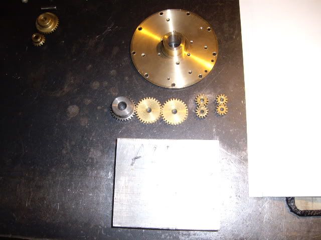
the parts for the oil pump, steel drive gear, two brass driven gears, and two pair of smaller gears to pump the oil in, and then collect it and pump it back out.  The plans call for the aluminum blank to be turned round, the machine work done, and then the pump cut out to its proper shape when all the details have been machined.  I didn't want to waste a perfectly good piece of stock so the piece I'm using will be less than round, but have all the area where details are machined in, just pretend its round when you see it in the chuck and later in the mill vise.

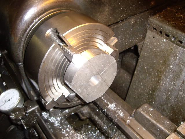
the blank, mostly octagonal

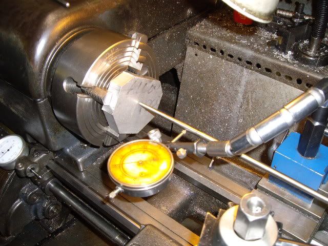
centering the blank with a rod and an indicator

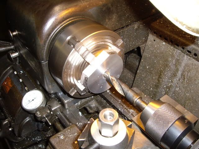
first side faced and turned down to 3.374, drilling before boring to a tight fit on the main bearing

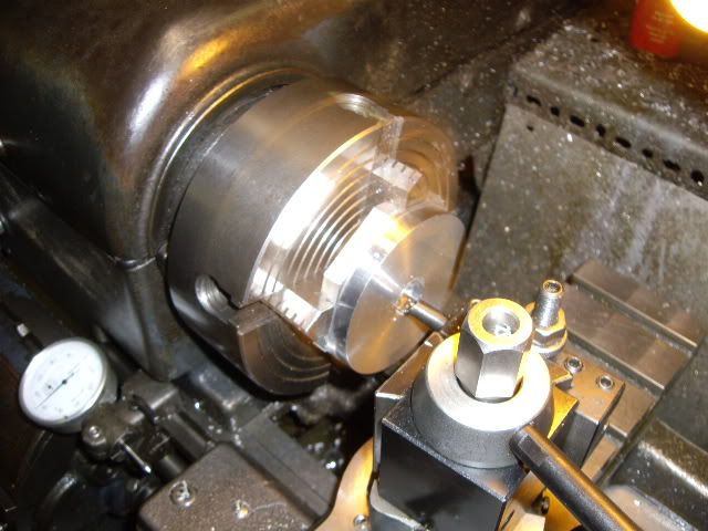
first cuts boring to fit the main bearing
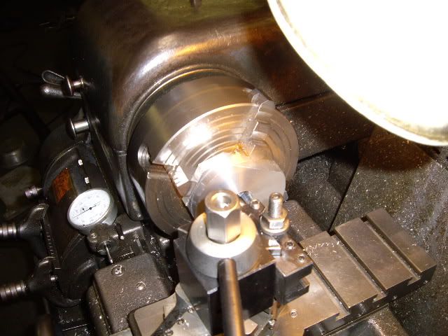
more boring

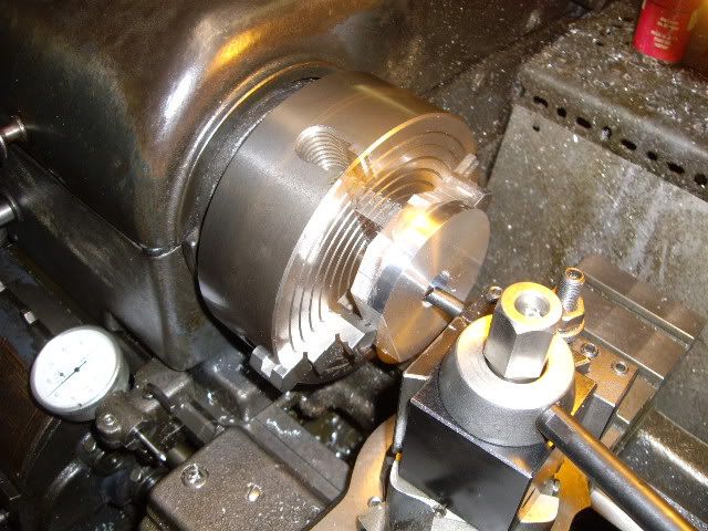
final cut, blank flipped and centered, o.d. turned to match first side at 3.374

second side, ready to be faced down to final thickness of .468

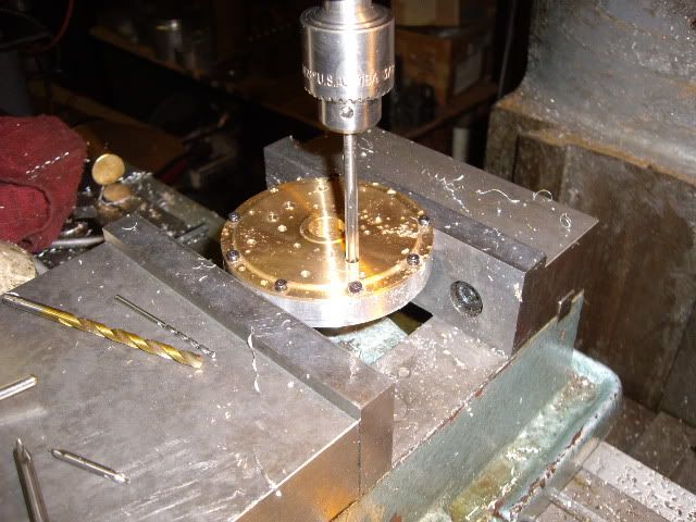
blank set up in the mill vise with parallels which are removed, for drilling and tapping mounting holes for the rear main bearing

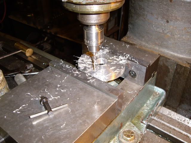
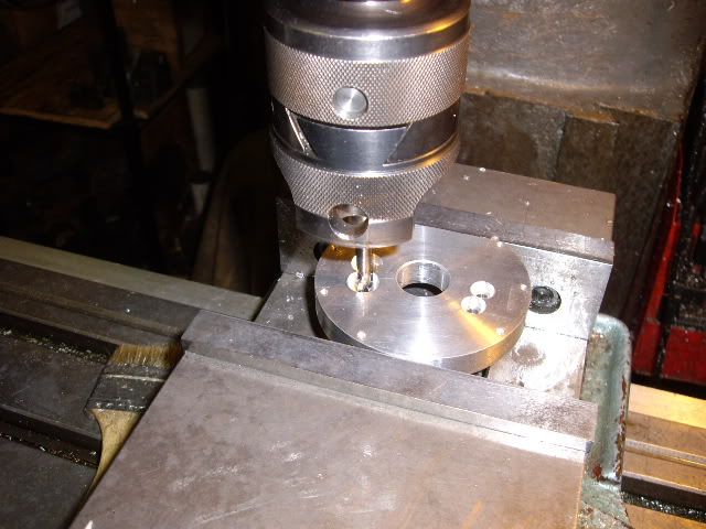
rear main bearing bolted in place for line drilling and reaming oil pump shaft holes through bearing and pump body

each of four holes is center drilled, drilled and reamed to ensure accuracy

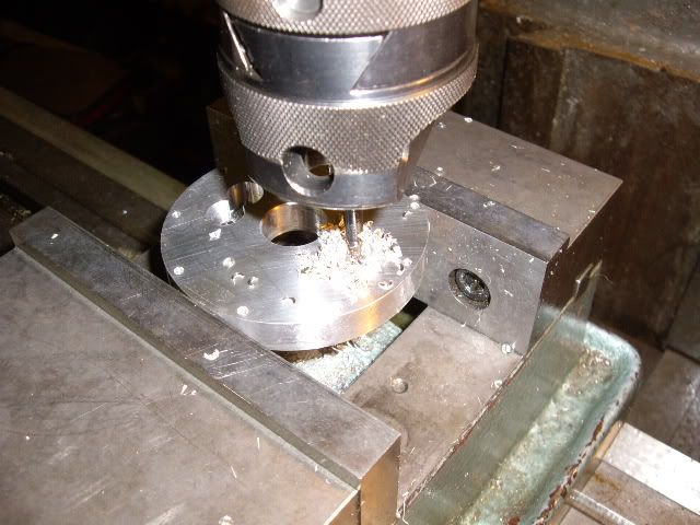
reaming through the main bearing and the pump body to ensure alignment

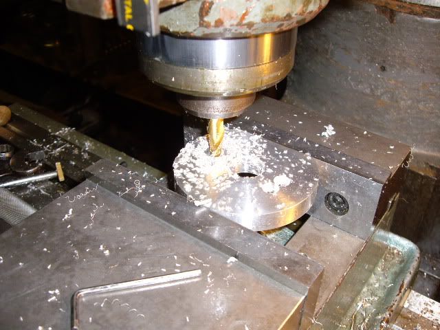
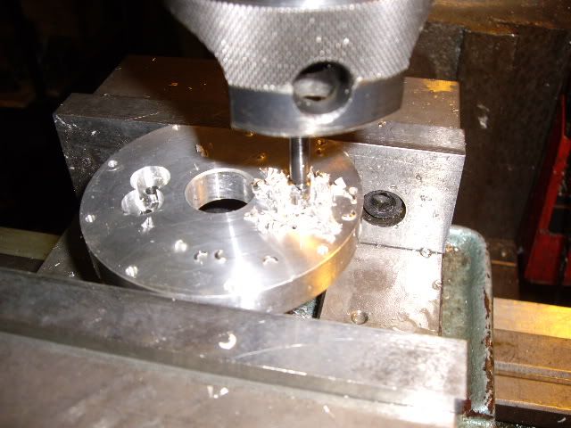
pre-boring one of the gear cavities with an end mill

another cavity pre-bored.  final fit will be half a thousandth over the gear size

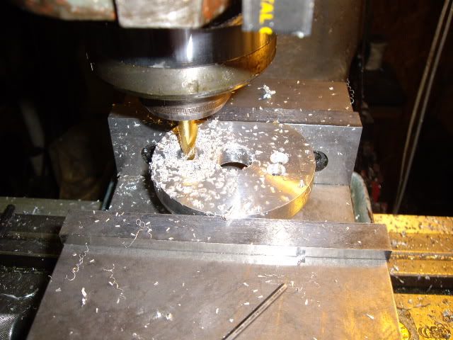
finish boring the scavenge pump gear cavity

finish boring one of the pressure pump gear cavities

finish boring the second pressure pump gear cavity

rear main bearing with all the oil pump shaft holes line reamed in place.  what is left is drilling the pump body for its passages, cutting it to profile, drilling the crankcase with the main bearing and pump in place to fit the pump to the crankcase and ensure free movement of the oil.


Rob.Wilson

  • Guest
Re: a nine cylinder radial engine, plans by "ageless engines"
« Reply #124 on: May 29, 2010, 04:49:26 PM »
Hi MJ

What's the frame for ?   how dose the head stock fit to it ? is them Suzuki rims you have there ?

Those are well fitting joints ,, you will get a nice clean weld on em  :thumbup:


The oil pump is looking great  :bow: :bow: :bow: :bow: :bow:

Regards Rob