I decided I'd be a good husband and stay in with the wife on Friday night - actually I was knackered but she doesn't need to know that!

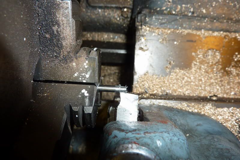
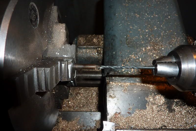
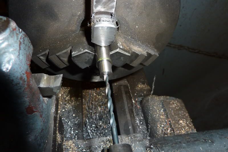
Started making the valve rod. This was just a bit of 1/16" stainless rod with a thread on each end. The thread, unfortunately had to be 10ba (bit small for my liking). 1/16" is too small for my lathe chuck to grip so I had a cunning plan, or at least I thought I did... hold it in the pin chuck:
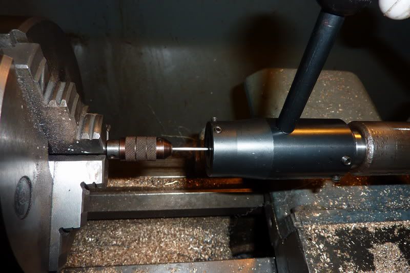
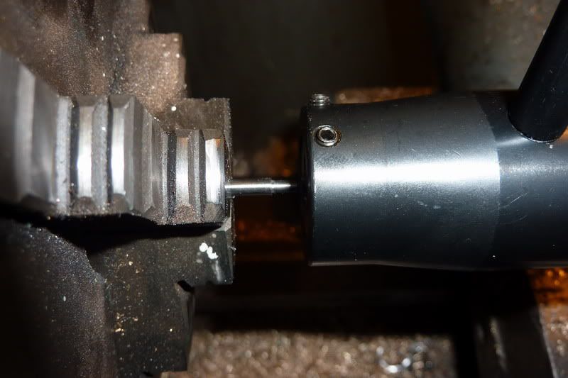
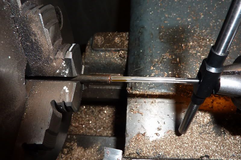
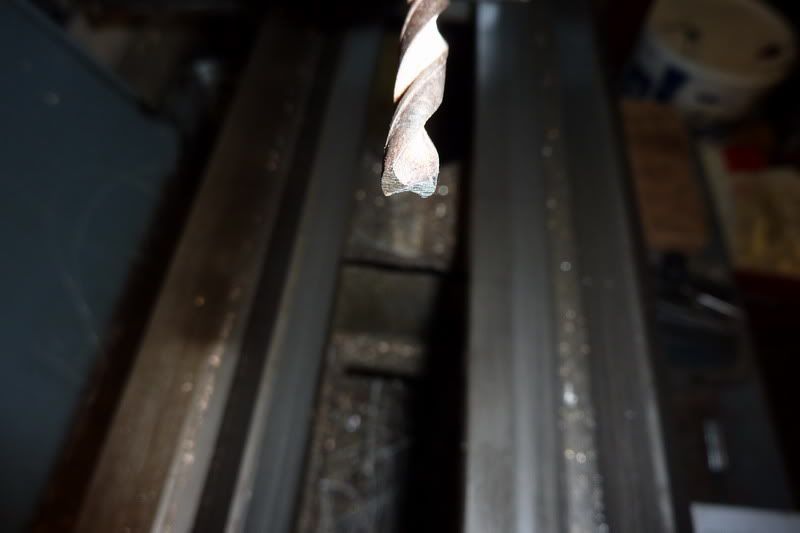
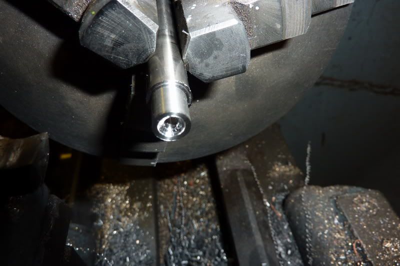
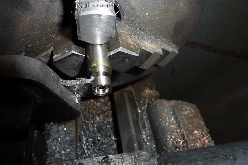
but this didn't really get a good enough grip. The collet was just too big so it slipped. So put the drill chuck in the headstock:
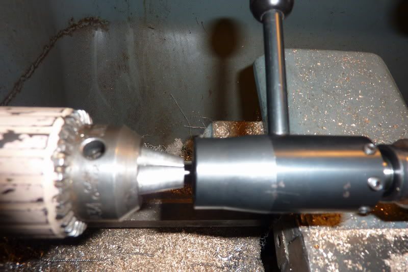
Worked this time. My new Soba 10ba die from the set I got for christmas didn't seem to be working very well though so used an old presto one and that worked!
Using 10ba also meant that I didn't have any nuts. I found one then had to drill another out that was even smaller!
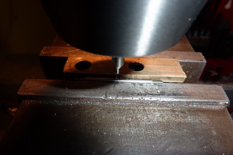
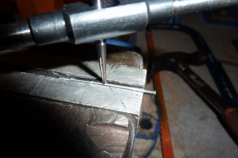
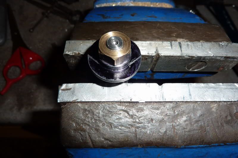
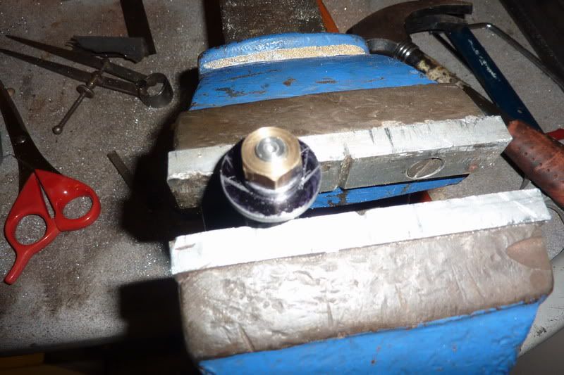
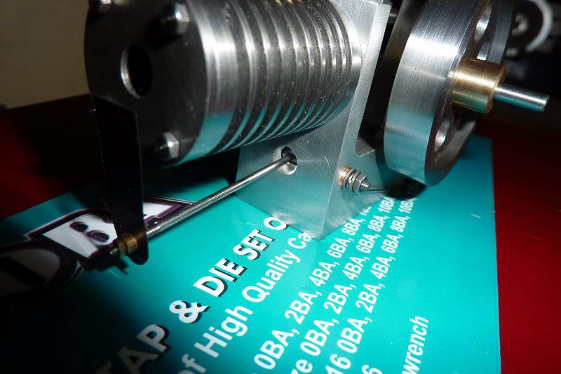
Tapped in vice as couldn't feel what was happening in lathe:
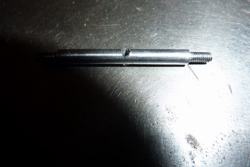
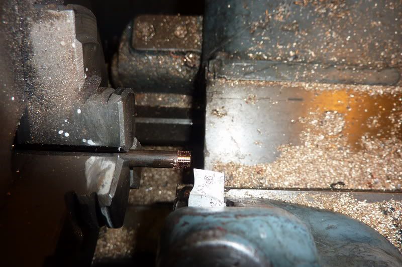
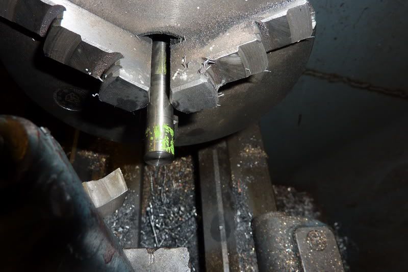
The next thing to make was the valve rocker shaft. This was from 1/8" silver steel. First had to turn ends down for 8ba:
Then cut the threads:
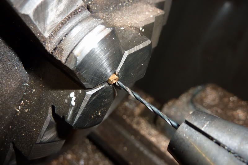
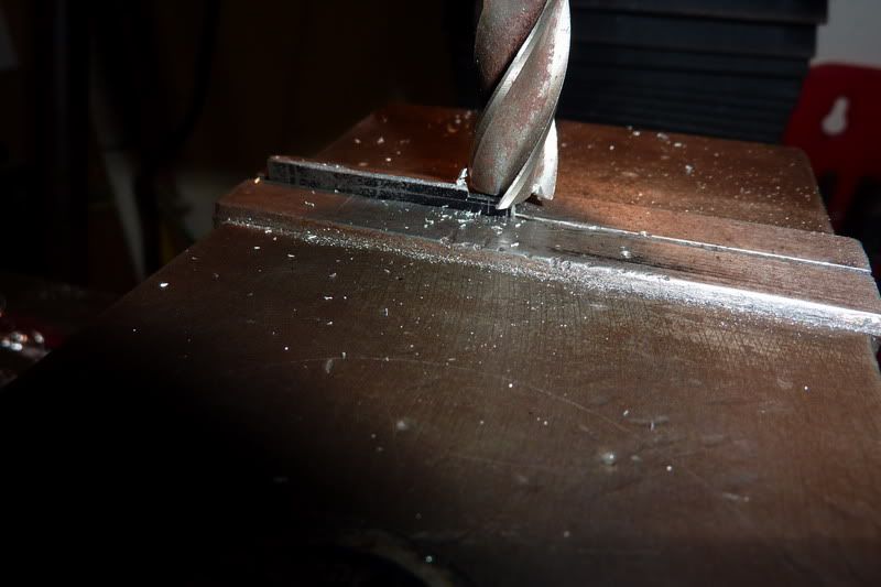
Then had to think of a novel way to clamp in the vice level - this is the heath robinson way I came up with, rested on a parallel and used a bit of packing in the jaw to grip. Here I am centre drilling:
Seemed to work reasonably well, drilled out to tapping size and started tapping:
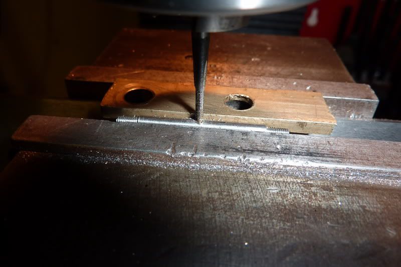
I was just thinking, this tapping lark in the milling machine is ok as long as use a low speed and oil and keep winding in and out... then ping!!!

I don't really know what I was thinking, 10ba in silver steel under power? Really?! I started it off with the taper ok so I should have taken it out at that point to finish by hand but no, I had counted my chickens so to speak!
Luckily I managed to punch the tap out with a bit I ground off the end of the tapping drill. I thought I had a pic but can't find it. I had actually drilled it a size smaller to attempt to get a tighter fit so that won't of helped, but it helped save it. It had only tapped a couple of threads so I opened it up to the proper size and tapped again, I hasten to add in the vice this time!
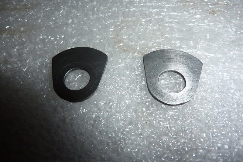
This was before de-burring:
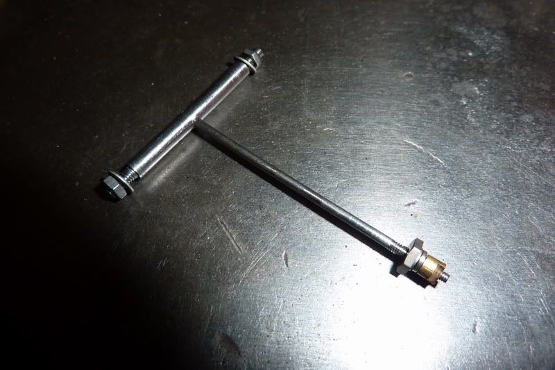
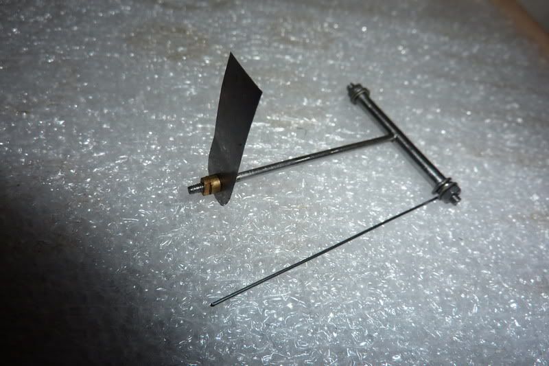
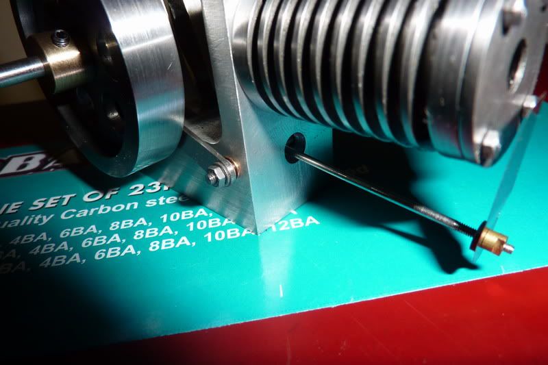
Assembled with rod and nuts:
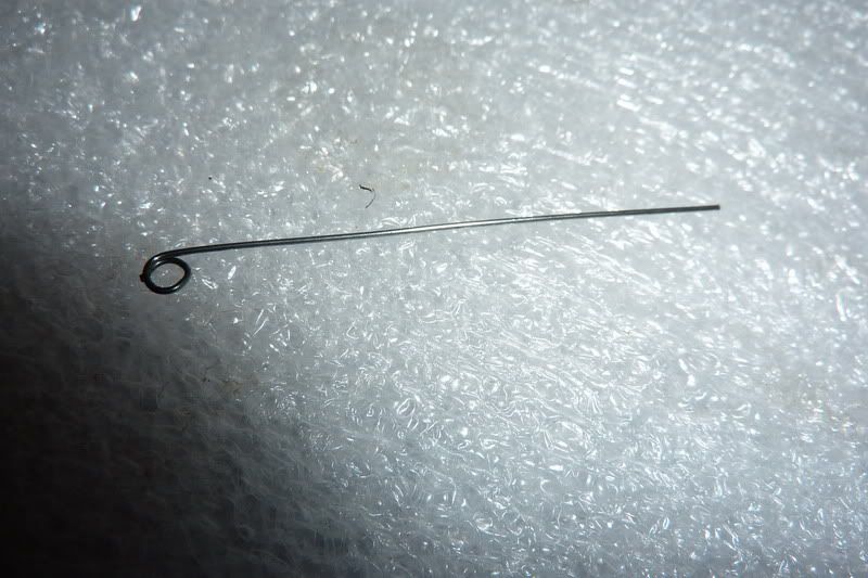
I then made the spring as was running out of time, that was nice and easy:
There's the assembly with the spring:
Forgot to mention that this was during the day on Saturday afternoon, I was allowed into the workshop for staying in the night before! The intention was to go back in later that night after watching a bit of silly sat night TV but I was too tired and only managed a bit. Did the valve shaft bushes.
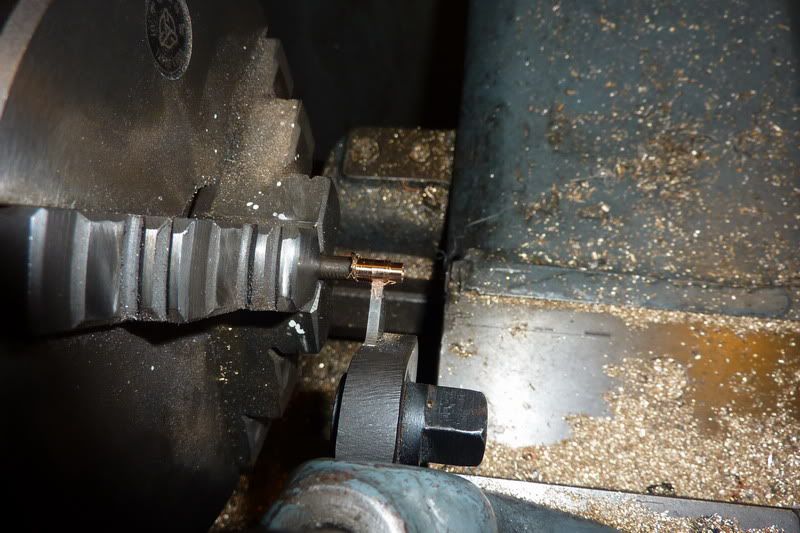
Drilling the rod. Think it's phosphur bronze but not sure, it came off a set of old scientific scales I think. It's sort of coppery and seems soft to turn? Anyway, it's the same stuff I used for my bushes on the ridders flame gulper.
Reaming 1/8" with my other christmas pressie:
Turning down to size. I wanted a light press fit, if too heavy it would crush due to thin wall and my 1/8" dia would be no more!
Finally parting off:
I thought the parting off was going badly as it kept leaving a pip (even though it was dead on centre) but luckily the pip just crumbled away and it was ok after a couple of twists by had with a countersink:
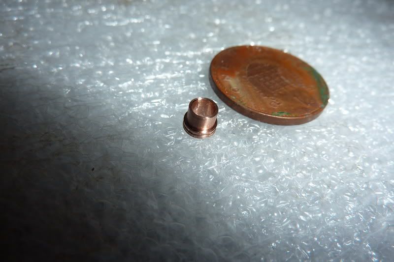
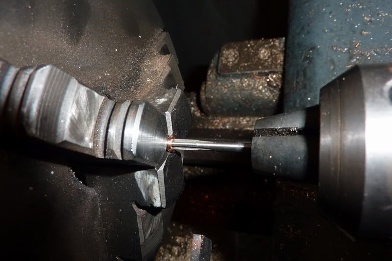
Then I tried the shaft in it and it was too tight! Then I remembered what Bogs told me about hand reamers having a longer tapered section, but I had reamed it blind so put it back in the lathe and reamed right through:
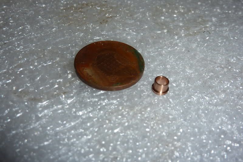
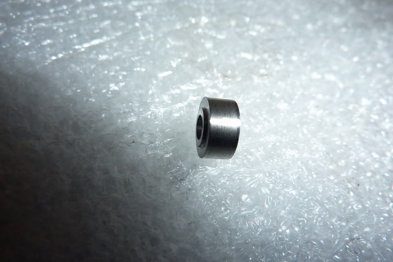
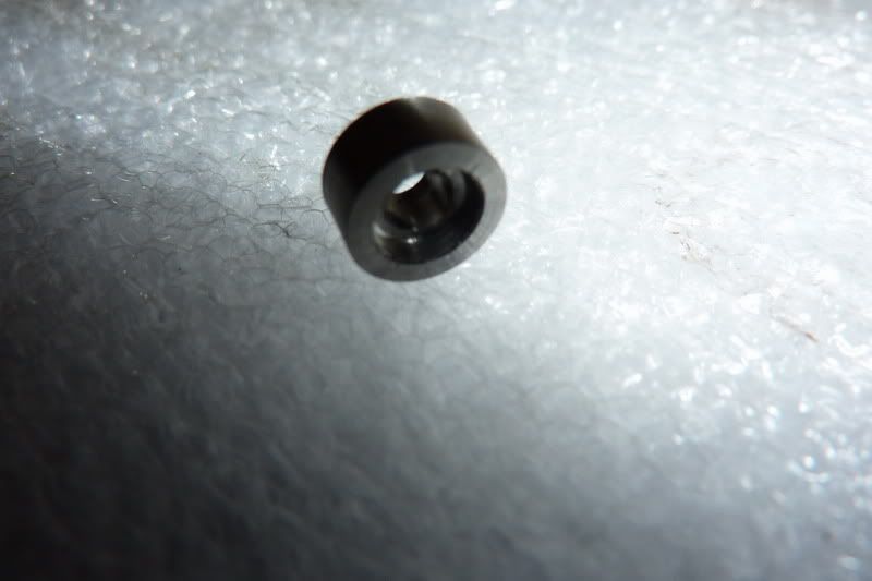
Another thing I noticed was that despite me being careful and using the graduated dial on top slide to make sure I parted off the right amount, it was coming out over size. I wasn't too concerned about this but when I started looking at the drawing, it was critical, the shoulder had to be 0.025" so that the shaft would protrude slightly at each end so I had to skim this down. Here is the finished bush:
Once I'd done the same for the other one, I'd had enough and quit while I was ahead. I just pressed the bushes in with a dab of loctite.
On Sunday I was allowed in the workshop during the day again ... what's going on?

!
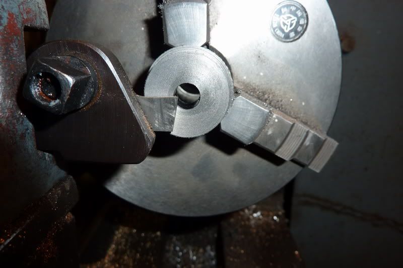
So I set about making the cam(s). These are 1" diameter and 0.047" thick. I decided the best way would be to turn a bar to 1", drill, ream and part off. I had a little short length of cast iron I thought would be good as I know it's easy to part!
Facing off:
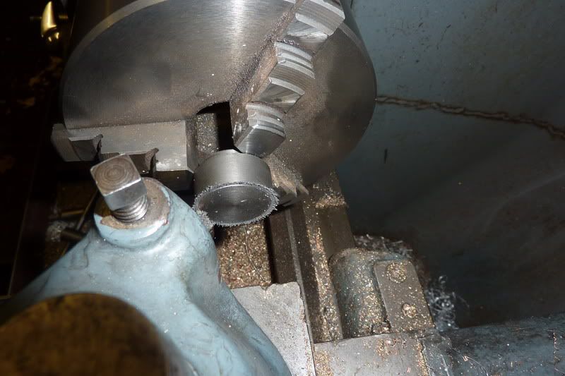
Turning to size:
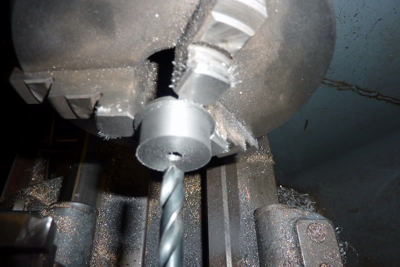
Centre drilling:

opening up:
by the way, what do you leave on there to ream? Some people say make the reamer work, some people say just a smidgin ... I drilled 7.5mm for the 5/15" reamer I think and it seemed about right?
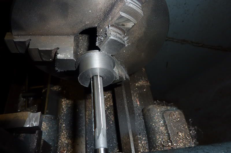
Reaming:
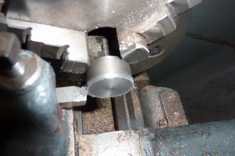
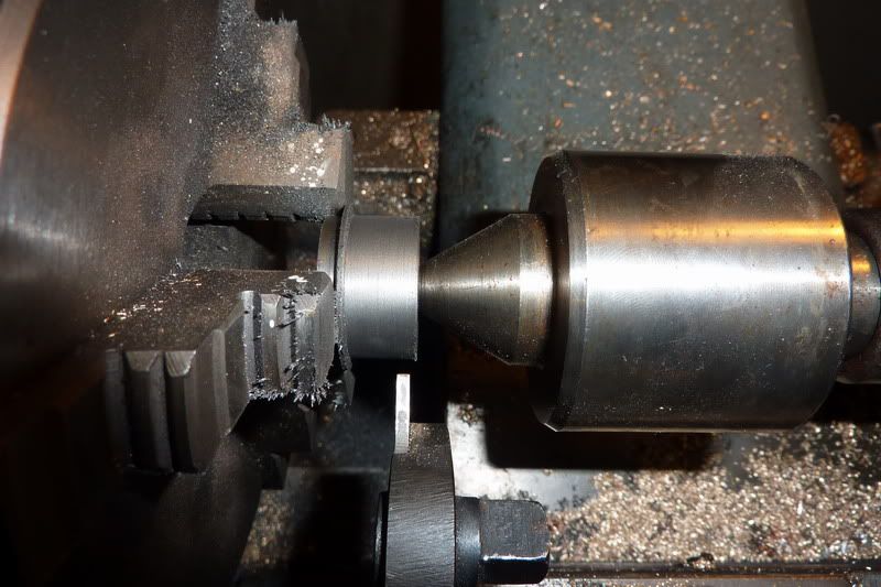
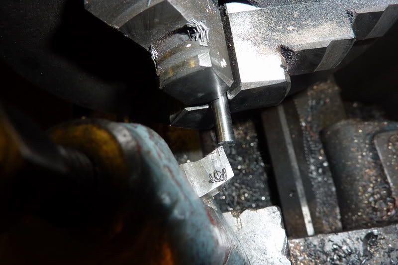
Then i set my parting tool up, looking from this angle I quickly realised you don't need to have much sticking out:
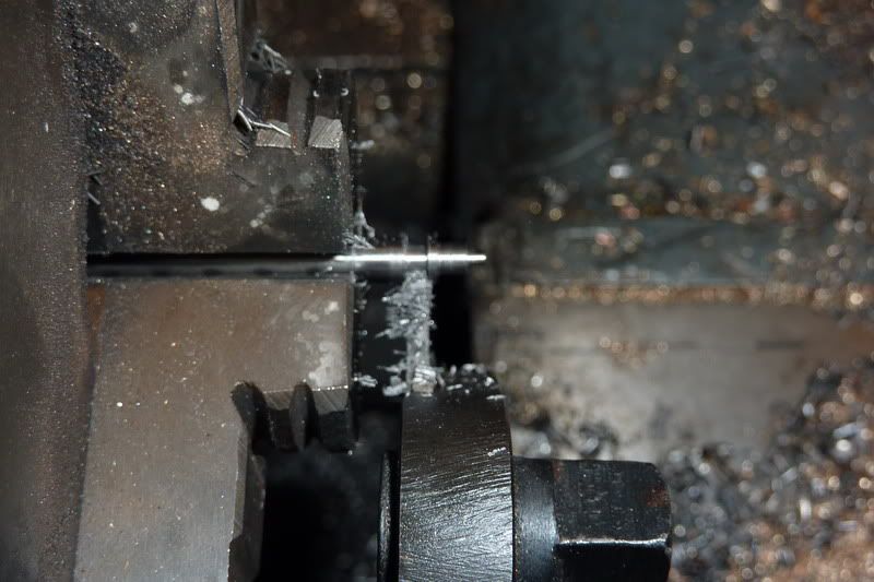
Parting off, used the centre as I wasn't gripping on much so remembered the advice from last time:
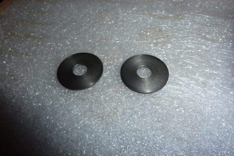
Here are the two blanks. One turned out 0.049" and the other 0.045" - oh well, think it'll do though!
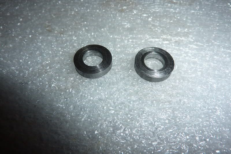
The radii on the bottom of the cam was 0.300" so I set about making 2 filing buttons of 0.600" diameter with a 5/16" hole through the same. I took photos but just realised the entire operation was exactly the same as the cams, just from steel and a bit thicker! The only thing new was that it was the first time I've sucessfully parted steel

I should have mentioned that I luckily remembered about the arbor I'd made for the flywheels which was the right diameter to hold it. With a bit of foresight, the od of this could have been made the same thereby incorporating filing buttons, but I had made mine from hex bar to index for the flywheel holes.
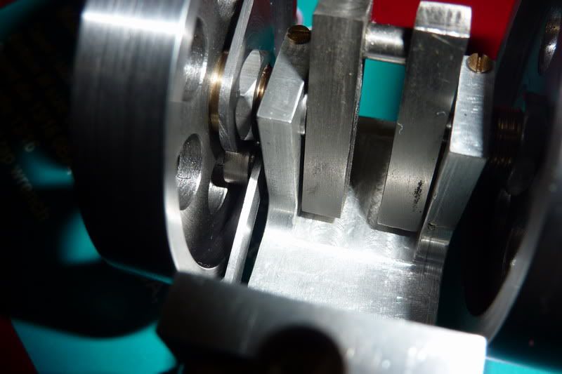
Here are the blanks mounted on the arbor with filing buttons and marked:
I thought, that looks wrong some how, and another look at the drawing confirmed that it was. The 110 degrees duration is shown in a funny way, so I interpreted what it meant and re-marked. You probably can't see it very well.
I thought I had a couple more photos but I can't find them. Anyway, I just hacksawed most of it away with junior hacksaw and filed the rest. The filing buttons didn't really work as they were just steel and not hardened but were there as a visual guide I suppose! I fear I may have taken a bit too much off so not sure whether the valve will be open long enough. Will see.
Sorry, it's a long post this ... need to update more frequently in future in bite sized chunks!
Next was the roller, pin and arm in that order.
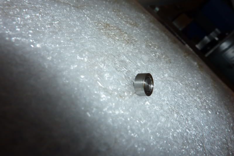
The roller was from a bit of stainless steel:
Facing:
Turning to size:

Drilling:
I decided I'd have to grind a drill flat to square out the counter bore for the pin as didn't have a slot drill or end mill small enough:
Drilled with right sized drill first:
Then flat drill before parting off:
I tried to be clever when parting to give it the 1/64" step which sort of worked but I did my calcs wrong and it ended up too long anyway. Hadn't read drawing properly and added 1/64" to overall length. To that had to come off. Needed to ream it through anyway though:

Here are a couple of pics of the finished roller:
Parting the stainless was worse than the mild steel - tended to chatter a bit, prob had speed or feed wrong.
Onto the pin, simple turning job but had to be the right dimensions again.
Facing:
Turning bearing surface:

Turning pin:

Parting:
Finished:
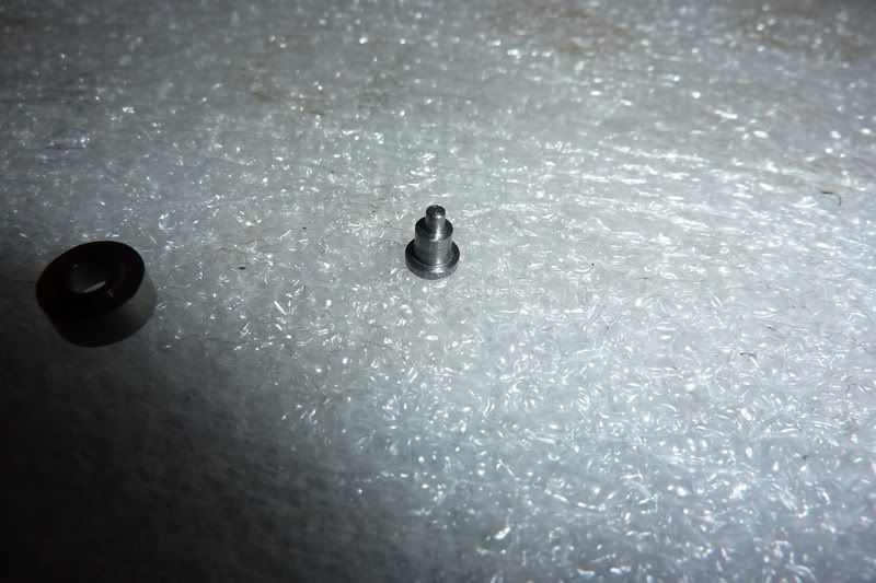
Assembled into roller:
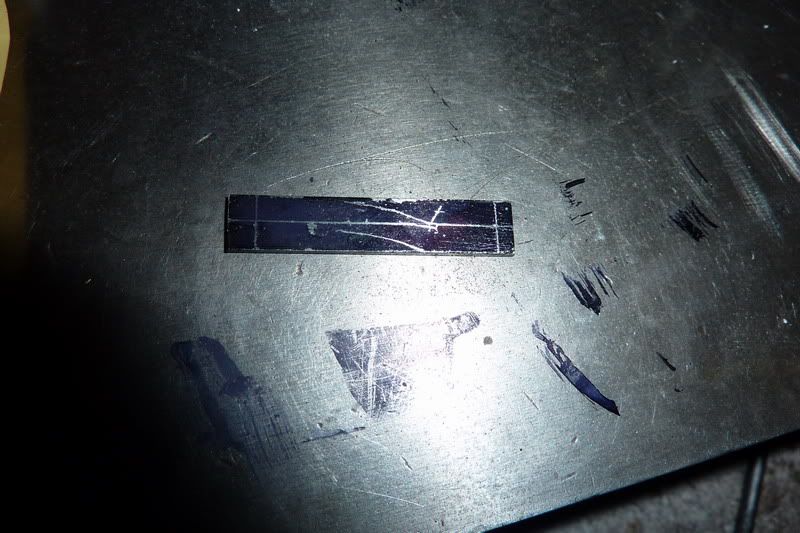
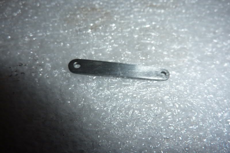
Now the arm, which would complete the whole valve assembly. I was going to use some 1/4" square bar, drill the holes and try to split it giving me 2 components but I decided that was destined to fail and I was making hard work of this. So I routed around and found some rusty steel sheet just the right thickness. Had a bit of straightening to do then cut a bit off.
Squared up in milling machine:
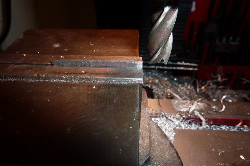
Here it is:
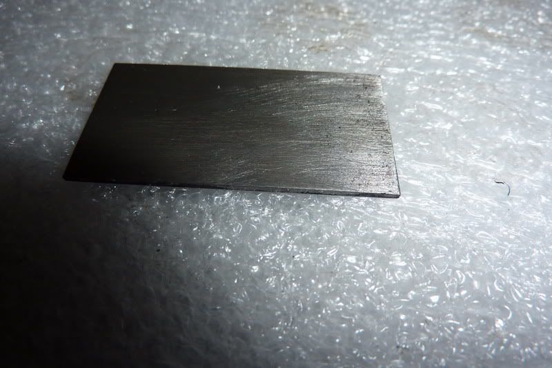
Marked it up:

Cut off and squared it up again:
Then had to re-mark it:
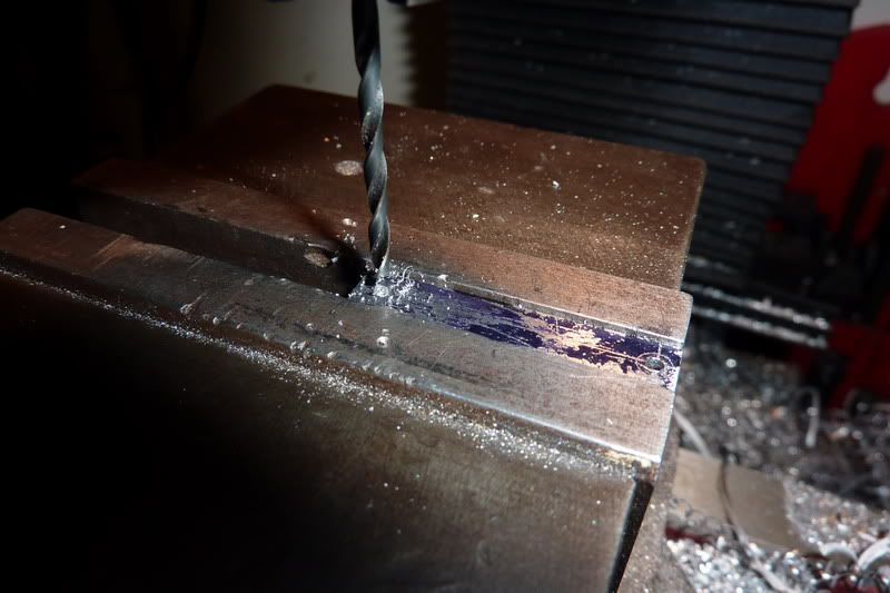
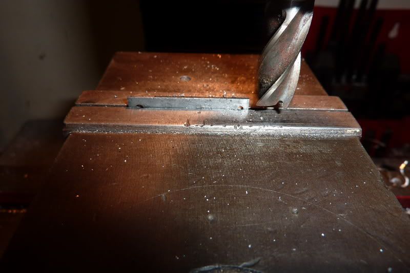
Drilled holes:
Then, by eye put at an angle in vice to mill angled sides. I didn't just do it willy nilly but thought I'd align the centre of the big hole and the bottom of little hole with the top of the vice jaw which would give the required offset.
After a bit of filing, it worked pretty well:
Then assembled the pin and roller onto it:
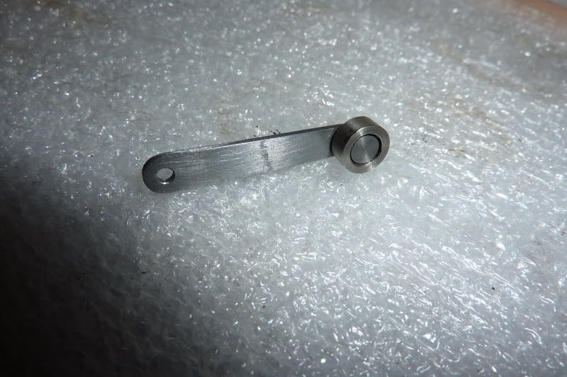
The idea was to peen over the pin, but without a ball pein hammer or rivet snap I had to use a nail punch, which worked well enough. I was really impressed with the roller, it spins over almost like a ball race but a bit looser. Probably due to the relatively hard metals it's made of.
That's about as far as I've got. Still on track, just the piston, rod & big end, burner and wooden base to complete. I've decided against the metal base (again!). I was going to make a brass one and machine turn it but I decided you can only see 3/16" all around so it's not worth it and it's pointless to boot!
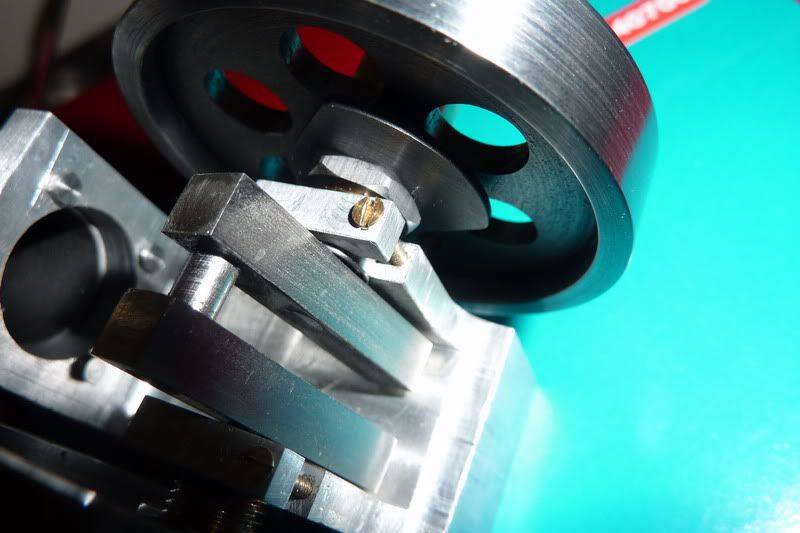
Here are a few snaps of the assembled engine so far. What a fiddly job that was
shame it's got to come back to bits!

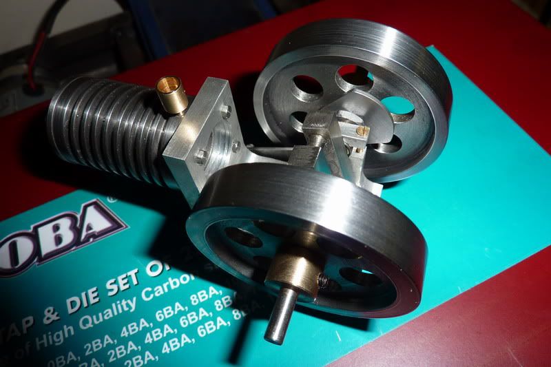
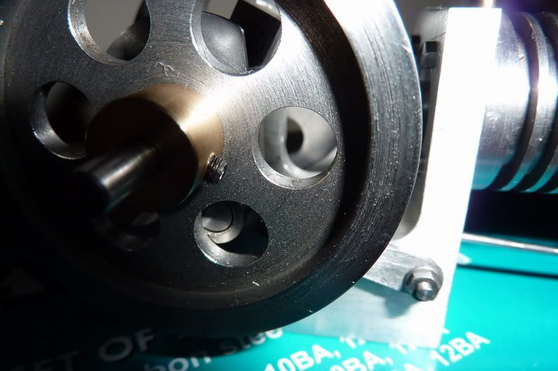
Getting nearer to the elusive finishing line!
Nick


