Author Topic: 'Poppin' Flame Licker  (Read 77674 times)

Offline andyf

  • In Memoriam
  • Hero Member
  • *****
  • Posts: 1795
  • Country: gb
    • The Warco WM180 Lathe - Modifications
Re: 'Poppin' Flame Licker
« Reply #75 on: March 19, 2010, 05:24:17 PM »
Sale, Cheshire
I've cut the end off it twice, but it's still too short

Offline NickG

  • Madmodder Committee
  • Hero Member
  • *****
  • Posts: 1890
Re: 'Poppin' Flame Licker
« Reply #76 on: March 20, 2010, 06:20:55 PM »
Thanks Andy, could be another option if I can't do it and they would supply just 1.

Looking forward to seeing you finishing yours off Jim.  :thumbup:

Nick
Location: County Durham (North East England)

Offline NickG

  • Madmodder Committee
  • Hero Member
  • *****
  • Posts: 1890
Re: 'Poppin' Flame Licker
« Reply #77 on: March 24, 2010, 07:38:00 AM »
Well, made a little progress last night, thanks to all the advice I should be able to have a better stab at screw cutting soon.

I made myself a little tool holder 3/8" diameter from some hard octaganol steel that used to be a chisel I think. It's very stiff, was hardly flexing at all with a 0.020" cut 2" from the chuck. Should be good for boring although I guess there are other factors like getting any resonance through it - will just have to try it before I can comment on that though. Only stupid thing I did though, when I drilled the cross hole I forgot to drill it parallel to a flat  :doh:  :doh:  :doh: what a numpty, I'll have to mill new flats on the gripping end now!

My plan is to use 3/16" silver steel which I can turn a taper on to get the angles accurate, face to length then mill down to half section - much the same way as a D bit. The round section should give me appropriate clearances by default apart from front and top rake which I can grind on then harden it.

The tool bit will be secured with a 5mm cap screw from the end. Will post some pics up at weekend and any trial cuts I make. I may have to change the material for my nut to something softer though as I said before.

This will also do as a little boring bar as I've needed one for a while.

So not much progress but a little. If I can't sort the vice I may be able to get the tool room at work to help out! Then back to the engine.

Nick


Location: County Durham (North East England)

Offline madjackghengis

  • Hero Member
  • *****
  • Posts: 717
  • big engine
Re: 'Poppin' Flame Licker
« Reply #78 on: March 24, 2010, 09:05:42 AM »
Hi Nick,  if you run into chatter problems with your boring the thread, you can take your top slide, turn it parallel to the ways, and you can machine a shallow cut, then with the next cut, move the cutter ahead a bit, say ten or twenty thousandths, and take a cut at the same depth, then move the top slide back for the next cut, just making sure you stop doing this as you approach the total width of the inside thread.  This lets the cutting tool cut on two sides at a time only, and can relieve pressure, and stop chatter.  It works well with a large acme or square thread as long as you keep good track of where the cutter is relative to the cut.  Old large allen wrenches make good cutters for such jobs, with the angle head already there, and good tool steel.  Sometimes you need to case harden the very tip, if you're cutting in hard steel or the like, but otherwise, they are hard enough for most jobs.  Looking forward to seeing you back to your vices, as all men ought to be :beer:Mad Jack

Offline NickG

  • Madmodder Committee
  • Hero Member
  • *****
  • Posts: 1890
Re: 'Poppin' Flame Licker
« Reply #79 on: March 24, 2010, 11:09:24 AM »
Thanks madjack, I came across the method you described sounds good. Good idea with the allen keys with the crank already there, never thought of that!

Nick
Location: County Durham (North East England)

Offline NickG

  • Madmodder Committee
  • Hero Member
  • *****
  • Posts: 1890
Re: 'Poppin' Flame Licker
« Reply #80 on: January 07, 2011, 02:55:48 PM »
Well, it's been almost a year but I'm finally going to get back onto this project tonight! Lets see if I can get these working, if they do, my Dad will get one for his Birthday in March instead of ebay getting it to make up for the non-working Tiny Stirling he got for Christmas!

Right better get out there armed with the camera, I think when they get looking more like engines I'll become more motivated!

Nick
Location: County Durham (North East England)

Offline NickG

  • Madmodder Committee
  • Hero Member
  • *****
  • Posts: 1890
Re: 'Poppin' Flame Licker
« Reply #81 on: January 07, 2011, 05:46:25 PM »
I felt sure this morning that I was going to go into the workshop tonight but after a week at work I was considering having a rest and going in tomorrow - glad I forced myself to get in there. Only made a little bit of progress but better than nothing.

When I left this project I was milling the frame which is from solid alloy bar and my vice broke. A while back when I started the 7 1/4" loco I managed to do a bodge repair to the vice which seems to be holding up (touch wood). I then got about 1/2 way through the loco build and got bored, then got  :proj: and decided to make a tiny stirling - that didn't work, so back onto the two poppin flame lickers I started almost a year ago. 2010 proved not to be a very productive year in the workshop, lets hope 2011 can be!

The frame went back into the vice to mill out the middle leaving the radii, roughed it out first:


Other side and getting through it now, I wasn't really enjoying this and contemplated handsawing most of it out - but that was taking even longer with an abrafile!


Taking the finishing cuts and climb milled with no extra cut on which gave a decent finish:


That's the profile milled out and de-burred:


Now I had to flip it in the vice so it was upright and mill to size before milling the slot for the crankshaft. I had a bit to cut off the top of the bearing supports and a bit off the over all thing so marked that out.


I hacksawed a bit off the top of the bearing supports to save me milling loads off.  :doh: Nearly hacksawed on the wrong line at first, the lower one is for the bearing bore - that could have been a disaster!


Back into the milling machine but upright as I said to mill to height:


This is about where I left it tonight as am a bit tired, I've de-burred it and have it clear in my head what to do next thanks to Jim's build notes. I need to drill and tap the holes for the bearing pinch bolts, mill the slot for the crankshaft. Saw off parent stock, invert in vice and finish the cylinder face. Bore cylinder face and transfer bolt pattern from cylinder cover. Flip in vice and mill slots in bearing supports. Finally flip upside down to drill and tap some mounting holes.

I don't think I'm going to bother with the thin metal base, don't see the point really, it can go straight onto the wood.

Thus far I've made 2 of each component but now I'm deliberating whether to drop onto one engine and progress more quickly to keep me interested. Or just battle on and make another frame. hmm ....

Nick

Location: County Durham (North East England)

Offline jim

  • Sr. Member
  • ****
  • Posts: 441
  • Country: 00
Re: 'Poppin' Flame Licker
« Reply #82 on: January 08, 2011, 01:31:30 AM »
looking forward to the next instalment
if i'd thought it through, i'd have never tried it

Offline NickG

  • Madmodder Committee
  • Hero Member
  • *****
  • Posts: 1890
Re: 'Poppin' Flame Licker
« Reply #83 on: January 08, 2011, 06:53:22 PM »
Cheers Jim, thanks again for those bearings by the way.

Got a bit more done tonight. Wow, this frame is possibly the most complicated component I've made, it's not been difficult (so far -  :lol: tempting fate here) but a lot of work in it and still not finished.

First job was to drill holes for pinch bolts, these are - can't remember size but my equivalent is 10ba, so drilled down with No 54 then opened top out for clearance to No 50. Haven't tapped yet, will do that by hand later:


Then start milling away the middle to leave the 2 uprights. Here I just got it some where near the right width then took some small finishing cuts after:


Finished milling - took a while, actually I had a cup of tea in between as I thought I was going to get impatient and mess it up! Also thought I'd leave the machine to cool a bit.


Back in the mill on its side to drill holes for bearings, I centre drilled, drilled through 1, then picked a sturdy ish drill to go through to the other using first as a guide. Then opened up.


That's it drilled to final size - tried the bearings they are a sliding fit so should be perfect for screw just to pinch. Marked out position of valve pivot.


While it was on its side I drilled the hole for the valve pivot.


That is about as far as I got, just de-burred it.


Still a bit of work here!

  • Saw it off the parent stock
    Mill flat
    Bore large hole
    Transfer cylinder bolt pattern
    Drill valve rod hole
    Mill slots for crank to pass through
    Drill & Tap mounting holes
    Tap Pinch bolt holes

Don't know, maybe it sounds more than it is but I'd say at least another night on it. I need to think of how I can bore it to 11/16" Don't think I've got a drill that big, have a 5/8" end mill. Might have a look at drawings to see if it's necessary to go the same size as the cylinder bore.

Nick
Location: County Durham (North East England)

Offline madjackghengis

  • Hero Member
  • *****
  • Posts: 717
  • big engine
Re: 'Poppin' Flame Licker
« Reply #84 on: January 08, 2011, 11:11:42 PM »
Hi Nick, if you don't have a boring head, you can use a straight boring bar in a collet with a HS cutter sticking out, ground to appropriate angles, and adjust the tool out with a dial indicator or even just a stop and feeler gauge to get that bore.  That frame is looking good, ought to get the second one out while you're feeling good about the first one looking so nice :poke: glad to see you back on the "poppin", I'm looking forward to seeing and hearing it running, in tandem I hope. mad jack

Offline NickG

  • Madmodder Committee
  • Hero Member
  • *****
  • Posts: 1890
Re: 'Poppin' Flame Licker
« Reply #85 on: January 09, 2011, 04:26:47 AM »
Madjack,

Thanks for the tip - I honestly don't know why I didn't think of that. I was thinking of all sorts of stuff, making a custom boring bar with an offset drilled with packing (as I now know how to do that!) I didn't see the wood for the trees! I think I have a boring bar like that, just depends whether it's small enough, if not, I could use the one I made to fix the vice by chopping it off probably.

Not sure about making the 2nd frame, it's taking ages! I know you're right though, if I drop onto 1 I'll end up with 1 engine and a nice box of bits that'll never get a frame to go with!

Might take your advice then!

Nick
Location: County Durham (North East England)

Offline arnoldb

  • Hero Member
  • *****
  • Posts: 515
  • Country: na
  • Windhoek, Namibia
Re: 'Poppin' Flame Licker
« Reply #86 on: January 09, 2011, 04:02:40 PM »
Nick, good going  :clap:

And very good close-up photos by the way; I struggled to comprehend the size you're working at, until you showed the drill for the 10BA - tapping drill size for me is 1.4mm and clearance 1.8mm, so that gave a bit of scale.  You commented in my thread about machining marks - well, you are on the exact same level, or even better, with me from what I can see - nothing a bit of effort with files and emery won't clean up.
One thing I did notice is your drilled holes - a smooth surface with a kind of "screw-thread" marking across it.  That always puzzled me on my own work, until I realised I got that when I drilled through, and "quickly" removed the drill from the job.  Try a test next time; when you bring the drill bit back out of the hole, do it as slowly as you fed it in ;) - but be prepared for a slightly over-sized hole.

Build that second base as well  :thumbup: - I'm sure you won't be sorry.

Kind regards, Arnold

Offline NickG

  • Madmodder Committee
  • Hero Member
  • *****
  • Posts: 1890
Re: 'Poppin' Flame Licker
« Reply #87 on: January 09, 2011, 04:25:01 PM »
Hi Arnold, thanks for the kind words and advice. I'll try that with the drill, I have a feeling you're right, I probably withdraw the drill too quickly. I should have mentioned something about scale, keep forgetting to include the coins in the pics. I was quite surprised when I realised I'd need to tap the pinch bolts 10ba. Never threaded anything this small before and it's deep in aluminium so I'll have to be careful. I got some ba bolts for Xmas but 8 was the smallest, never thought I'd need 10. I've found a couple of counter sunk head screws which will do if they are 10ba. So some bits are quite small on this engine but the bore is actually quite big at 11/16". No progress tonight but some good news for me ... I've got 1 of the broken cars back. I found a similar forum to this for Renault Clio Sports and a local enthusiast took the car away, took my engine out and put his in for an unbelievable price! He's doing a conversion on his. Chuffed to bits!
Back onto this tomorrow, think I will do another frame and I've reconsidered about the base plate that goes under them, got an idea in mind for those.
Nick
Location: County Durham (North East England)

Offline sbwhart

  • Global Moderator
  • Hero Member
  • *****
  • Posts: 3530
  • Country: gb
  • Smile, Be Happy, Have Fun and Rock Until you Drop
Re: 'Poppin' Flame Licker
« Reply #88 on: January 09, 2011, 06:10:05 PM »
Nick

I think I've some 10ba you can have bought them because they were so small I though they were cute.
  :D

Stew
A little bit of clearance never got in the road
 :wave:

Location:- Crewe Cheshire

Offline NickG

  • Madmodder Committee
  • Hero Member
  • *****
  • Posts: 1890
Re: 'Poppin' Flame Licker
« Reply #89 on: January 10, 2011, 07:25:30 AM »
Quote
I think I've some 10ba you can have bought them because they were so small I though they were cute.

Haha! Thanks Stew that's be great - only need 4, don't think I'll be using that size any more. Can't remember if there are any on Mabel that small?!

Nick
Location: County Durham (North East England)

Offline madjackghengis

  • Hero Member
  • *****
  • Posts: 717
  • big engine
Re: 'Poppin' Flame Licker
« Reply #90 on: January 10, 2011, 09:00:14 AM »
Hi Nick, by the by, most of my small screws are salvage from old tape decks, CD players, hard drives and other parts from computers, and they are metric, mostly, but I get some salvage which is American thread on occasion.  I do buy when I have to, and usually by the box, as it's far cheaper that way, and there's always another small project.  With regard to your drills, I tend to use the mill brake, and stop the spindle to pull out tiny drilled holes, and avoid that odd thread look, but generally only with holes I need dead on size and don't have a reamer for.  I try to use either fillister head screws or allen screws as much as possible, as they put the pressure as straight down as possible, with counter sunk heads finding center off the counter sink, and occasionally the head will pull the piece it is in, off kilter because the counter sink is put in separate from the hole, and can pull to the side if allowed.
  It's good to see this set of engines coming together, I hope you've got a good bore and good pistons, so they start up fairly easily, and run well.  It seems that is the primary issue with the "poppin", as the valve gear seems pretty clear from interfering with the running, unlike the Blazer and some others.  It really seems to be very effective and I need to build one sooner or later.  Too many around to avoid that responsibility it seems.  Nice pictures of the frame, hope to see some of the boring for the cylinder soon.  :poke: mad jack

Offline NickG

  • Madmodder Committee
  • Hero Member
  • *****
  • Posts: 1890
Re: 'Poppin' Flame Licker
« Reply #91 on: January 10, 2011, 09:41:44 AM »
Cheers Madjack. I do have a set of metric taps and dies now so I can keep my options more open in future rather than stick down the ba route. I wasn't concerned about the rough finish on that particular hole as it will help grip the bearings. Might need a couple of marks putting in anyway to aid grip but will take yours and arnolds advice in future. I did notice it still taking material off the top hole as i was cutting / withdrawing from the bottom one so the top is probably marginally larger. I didn't have a 5/16 or 8mm reamer though.

Good point about counter sunk screws, I was only going to use those as I found a couple but I forgot to countersink anyway so i'll be better off with hex heads. I think they look more authentic on these old type engines.

I used lessons learnt on my Ridders flame licker and reamed the bores with plenty of oil at a slow speed so I'm fairly confident the bore is good enough. On that I just turned the piston and left it straight from the lathe (it gives a very good finish on a slow speed and feed for cast iron) to retain parallelism. Microscopic grooves are probably good at retaining oil too. However, I might try graphite pistons with the stuff that Ade kindly donated for my tiny stirling. I know somebody on HMEM used a graphite one to good effect.

Ha, that's what I thought - I had just finished my Ridders flame licker and thought those would be out of my system, but I was intrigued too much to attempt this more conventional type to compare the performance of the two!

I know I've just restarted this thread so it may have been forgotten where I was up to - check back at older posts for cylinders and other bits, I'd nearly forgotten myself!

Nick
Location: County Durham (North East England)

Offline NickG

  • Madmodder Committee
  • Hero Member
  • *****
  • Posts: 1890
Re: 'Poppin' Flame Licker
« Reply #92 on: January 10, 2011, 07:35:11 PM »
Been quite a long night and still a bit to go as this will take a while to write up!

Continuing with the frame for poppin..

First job was to saw the job from the parent stock.


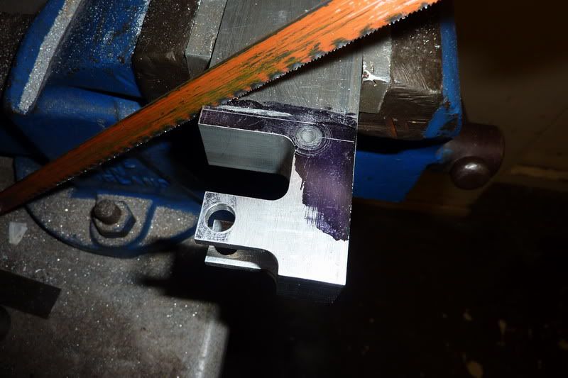
10 minutes with the hacksaw - I did such a good job I thought I'd just touch it up with a file instead of milling.


Just checking you're awake... I thought I'd try to get it  a bit flatter than that so put it in the milling machine and decided to flycut it rather than take loads of passes with a small cutter. Luckily the flycutter was still set up from when I skimmed the block originally.


Then it came back out to get marked up for all the holes. (large one for conrod to pass through, cylinder bolting holes and hole for valve rod) I decided that as the width of the standard was 1" and the cyl. cover 1" it was fairly easy for me to just position the cover and mark the holes through.
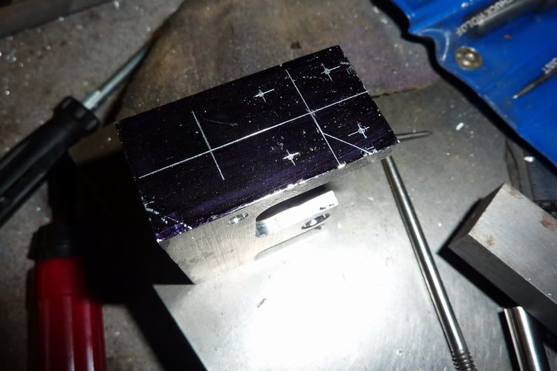
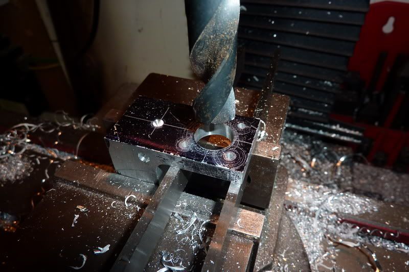


Spotting the holes.


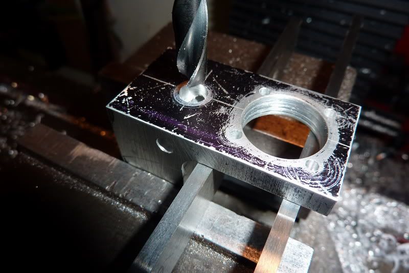
Then starting to open the large one up:


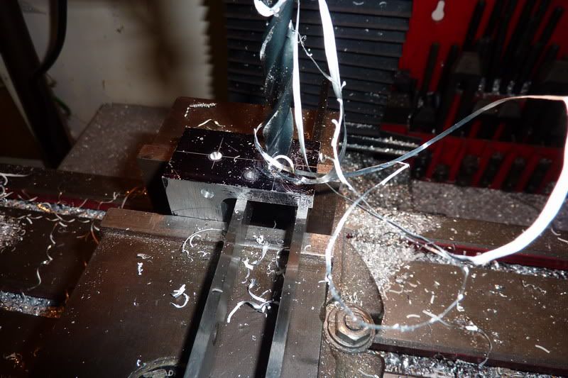
Drills getting bigger and scarier!


I decided to finish with the closes thing I had to 11/16", a 5/8" slot drill.


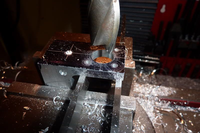
This worked really well and gave a good finish.


I was going to stop there as I would guess 5/8" would be big enough for the con rod not to foul. But then I thought, no, I better stick to the drawing as couldn't be bothered calculating stuff! So I found an old boring bar:


it happened to already have a tool in it. I just had to grind a bit away from the wrong end so it didn't interfere with me trying to measure it to get 11/16". I got as near as damn it to what would give 11/16", put it in the collet chuck and started boring!


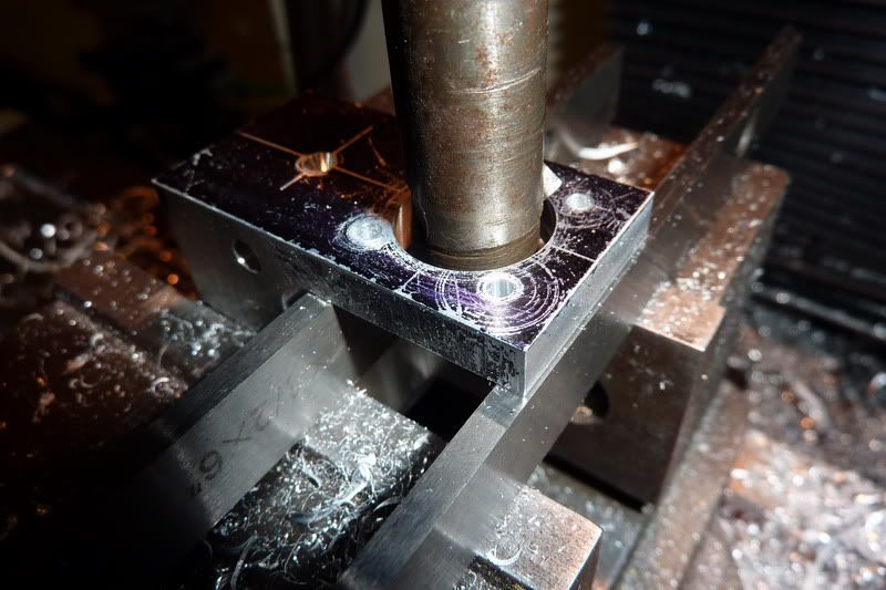
At this point I was pretty scared as it appeared to be wobbling about like a good 'un! No idea why it would do that but I think it was to do with the shape of the tool - it was a sort of v shape but with hindsight I think I should have had a virtually straight leading edge just with some rake angle and a slight clearance. The up shot of this was that it gave a rubbish finish. I think it was partly my haste using the tool that was already there and wanting to stop the operation as I thought I was going to ruin my component.


I quit with this while I was ahead (well, while nothing was broken!) with the hole at this point. I'll need to practice this boring lark on some scrap and might re-visit it if I get good results I think, or at least I'll get it right for the next frame.

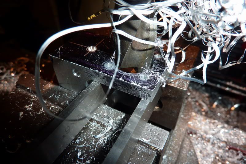
Next, another scary operation. Milling the slot through the bearing holes to enable the crank to pass through. I thought I'd try out my new slitting saw arbor and one of the saws I cunningly kept from my horizontal milling machine. The concentricity of the arbor or saw must be cr@p as you could visibly see the run out (about a mm or so!). I decided as it wasn't moving up or down it should still be ok and turned it by hand a few times with it touching the workpiece trying to get it into what I thought was the best position. I made sure I wasn't climb milling and that when I'd wound it all the way through it'd cut the slot in one pass.

As I neared the workpiece the tinging noise nearly made me have kittens, I thought it was just going to bend  the uprights but I thought with a decent speed (about 400 rpm?) and a slow feed it should be ok. I nearly made a massive booboo though. The slitting saw was 0.1" wide and the slot was to be 0.16". So I started off with the bottom edge 0.080" below the centreline of the bearing holes. Then I'd move it up 0.060 to do the second pass and widen the slot to desired width. If I'd have done that, it would probably have bent the top. Glad I remembered and started at the top first then widened at the bottom where it still had more structural integrity. Sorry, this is getting a bit waffley, anyway, it worked ...

I thought I'd tap the holes next. Another problem here, the 10ba tap is nowhere near long enough to go through the clearance hole and into the portion that should be threaded. It gave me 4 or 5 threads in there max before the shank started to foul - have no clue what to do here. I'll have to read the instructions to see if I've missed a trick.


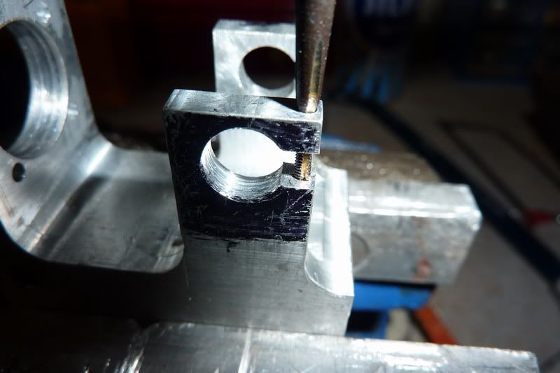
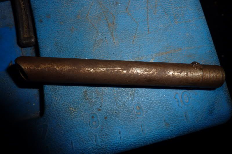
The last thing to do was to drill the 1/4" hole for the valve rod that meets the cross hole for the valve shaft:


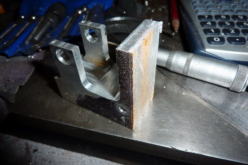
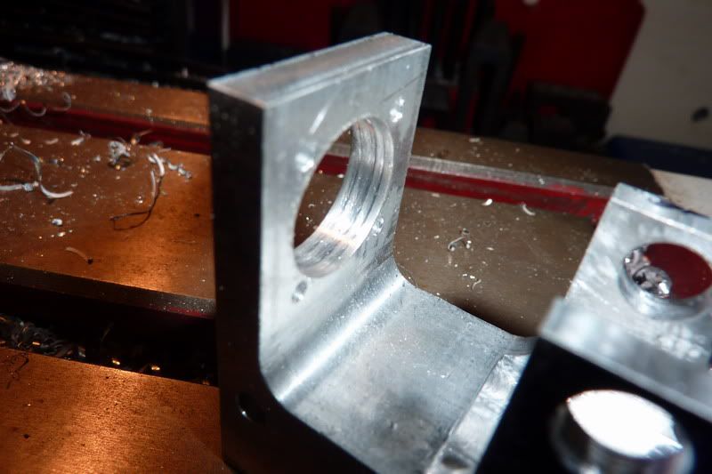
That went well. I cleaned the thing up a little and here is the finished standard or frame:


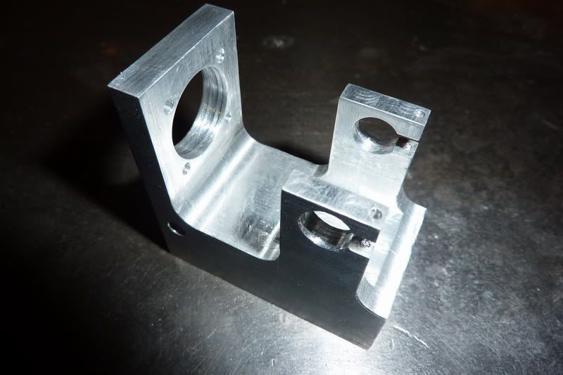
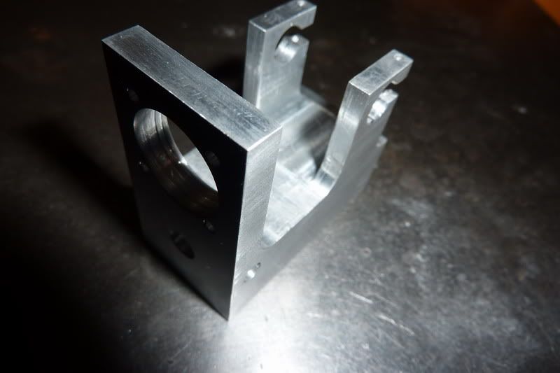
Actually it's not finished - I forgot to drill any mounting holes in the bottom but was too late to start, don't want to ruin anything due to being too tired!

I really don't want to make another one of these right now. I think I want a change of scenery so to speak so might crack on and make some other parts and come back to the 2nd frame!

Nick


Location: County Durham (North East England)

Offline NickG

  • Madmodder Committee
  • Hero Member
  • *****
  • Posts: 1890
Re: 'Poppin' Flame Licker
« Reply #93 on: January 10, 2011, 07:39:09 PM »
Oh, forgot to put this one in, a shot after flycutting:


 and I couldn't resist this mock up, this was earlier on before I'd (nearly) finished the frame!

Location: County Durham (North East England)

Offline sbwhart

  • Global Moderator
  • Hero Member
  • *****
  • Posts: 3530
  • Country: gb
  • Smile, Be Happy, Have Fun and Rock Until you Drop
Re: 'Poppin' Flame Licker
« Reply #94 on: January 11, 2011, 03:17:23 AM »
Looking good Nick, I liked the way you bored the stand to take the cylinder.

Stew
A little bit of clearance never got in the road
 :wave:

Location:- Crewe Cheshire

Offline NickG

  • Madmodder Committee
  • Hero Member
  • *****
  • Posts: 1890
Re: 'Poppin' Flame Licker
« Reply #95 on: January 11, 2011, 05:08:56 AM »
Stew,

Thanks but I think I rushed into boring the stand too much. I should maybe have made a custom boring bar. That one was too long and the v type tool that was already in it was no good - I think the angle started pushing, bending the bar rather than cutting cleanly. I fed it with the drill feed too which was too fast, maybe I should have fed it down with the spindle just nipped. Maybe the tool wasn't quite sharp enough either. Whatever I did, didn't seem to work very well at all. I don't think I need a boring head for the amount of times I do this, although guess then I could quickly and accurately bore to a good finish.

Does anybody have any other tips for boring like I did?

Thanks

Nick
Location: County Durham (North East England)

Offline madjackghengis

  • Hero Member
  • *****
  • Posts: 717
  • big engine
Re: 'Poppin' Flame Licker
« Reply #96 on: January 11, 2011, 09:59:23 AM »
Hi Nick, you're looking good there, getting along well.  The boring bar issue is almost always about the cutting tool.  Boring is inherently about doing something you need with the worst possible conditions of tools in that you have the longest tool holder, supported on one end only, and you're working inside, so you need extra "front" clearance on the bottom end of the cutter, to clear the circumference sector between the cutting edge, and the heel of the tool.  If the tool has a "shear" cutting edge, from a fair top clearance angle, appropriate front clearance, and like you said, going at the work pretty close to square on, with a nice radius, minimum size, fine finish, and the bottom of the cutter radiused for the clearance you need, and of course, the cutting edge back relief such that the edge is cutting "on plane" with the centerline of the spindle, you can expect a good clean bore.  The usual bit that's missed is the heel of the cutter, with it dragging through the already cut part.  Making sure your cutter has a smaller radius from top, cutting edge, to bottom, trailing, than the hole being bored will ensure this doesn't happen, unless your cutting edge is above the "plane" of the spindle centerline.  I use a fly cutter holder, with a tool ground to meet all the angle requirements to fit in my boring head, for boring Harley engine cases larger for big bore cylinders, and have tool bits just for that specific job.  A through cut, such as you've taken, can use the same form of tool bit a between centers boring bar uses, with the same parameters, angles and nose radiuses adjusted for the metal being bored.  I hope this helps a bit.  With regard to cutting the slots for the crank, you can cut such a wide slot by cutting most of the way through and leaving fifty or sixty thousandths in the back of the cut, taking both cuts, to get your width, and then do the final cuts from top and then the bottom, so you have support to the end.  You can even cut the last out by hand, and even up the slots with a hand file.  :bugeye: mad jack

Offline NickG

  • Madmodder Committee
  • Hero Member
  • *****
  • Posts: 1890
Re: 'Poppin' Flame Licker
« Reply #97 on: January 11, 2011, 10:55:54 AM »
Thanks madjack, I will follow this reply next time I bore something in the miller to get the tool correct.

I've just been looking at the poppin plans and it'd been so long since I did the cylinder I forgot, it's actually 5/8" bore! So I probably could have left the bore in the standard 5/8". I doubt the con rod comes within 1/32" of the bore in the standard so see no reason why it would need to be larger than 5/8".  :bang:

Just been compiling a list of what I need to do to complete an engine - it's bad enough for 1 engine, let alone two! I definitely want to finish both at some point though as if one goes to my Dad for his birthday in March, I want the other for my collection of engines. I think I have 7 nights work left so that means if I manage to get workshop time every night, one should be ready for next Tuesday - quoting timelines always puts the kibosh on things though!

Nick
Location: County Durham (North East England)

Offline arnoldb

  • Hero Member
  • *****
  • Posts: 515
  • Country: na
  • Windhoek, Namibia
Re: 'Poppin' Flame Licker
« Reply #98 on: January 11, 2011, 11:28:27 AM »
 :thumbup: Good progress Nick  :D

Before I built the boring head in my avatar, I had to do boring with bars similar to yours.  It takes a fine feed and not too great depth of cut; you can't hog it.  And a very sharp cutting tip helps as well, with suitable clearance on all sides.  It takes a bit of patience - and gets a bit ..erm.. boring  :palm:

 :beer:, Arnold

Offline NickG

  • Madmodder Committee
  • Hero Member
  • *****
  • Posts: 1890
Re: 'Poppin' Flame Licker
« Reply #99 on: January 11, 2011, 06:34:11 PM »
Ha, nice one Arnold  :lol:. Come to think of it, I had a 5/8" hole and I tried to take it out to 11/16" in one cut - that's 31 thou so quite a bit I guess, esp with the wrong, blunt tool and too much sticking out of chuck. Your boring head looks great by the way.

Didn't get much done tonight, was basically messing around but nevertheless did a few jobs that needed doing.

I cut the shaft away from middle of crank, drilled and tapped the holes in the base, tapped the holes in cylinder to mount and for cover, drilled and tapped the hole for the oiler, cut some bolts to length and assembled some bits.

Here are a couple of pics of the assembly. It's only now that I get a feeling for the size. I love the look of the engine but the more I look at it the more I realise it's not particularly well made. I just really hope it's going to work! Will just have to make sure I get all the critical bits right again.


Quiz night at the pub with mates tomorrow so there won't be any progress until thurs night now, hopefully i can crack on and get some bits made now some of those fiddley jobs are out of the way.

Nick

Location: County Durham (North East England)