Author Topic: building a new flame sucker  (Read 45218 times)

Offline madjackghengis

  • Hero Member
  • *****
  • Posts: 717
  • big engine
building a new flame sucker
« on: December 20, 2010, 11:56:44 AM »
Thanks to someone whose name I won't mention, posting a very tiny fly sized stirling engine on their build log, Nick, and then having to look at the other engines built by Herr Bettigue, and running across some of the most impressive engines I've ever seen, I was inspired to try to build a similar engine to one I found particularly interesting in how it runs.  I had a cylinder I'd drilled, reamed, honed, cut fins on, all for the purpose of finding out the quality of the cast iron rod I bought for another project, and was just sitting around, so I decided to use it, and start the build of this engine from something I never intended to use when I made it.
   I'm afraid it has been so long since I posted a picture from photo-bucket, I no longer know how to do it.  There seems to have been changes made, and I could use a bit of advice to get some pictures in this new log.  Any help would be greatly appreciated.   :bang: :bang: mad jack

Offline cidrontmg

  • Full Member
  • ***
  • Posts: 229
  • Country: pt
Re: building a new flame sucker
« Reply #1 on: December 21, 2010, 12:03:34 AM »
Photobucket has changed some, but not very much. Basically what you do is, log in to http://photobucket.com/
Click on "My albums" (to get the pictures where you want them), third menu item. You will land to "(MadJackīs) Album", that is, the root folder of your albums. Scroll down a bit, and on the right side, you will find (in black) "Sub-Albums" (if you have any) and next to it, in blue text, "Create new album". Click on that, and a new pop up window opens that says "Create new album". First line is "Name your new album", there you could put (for instance) "New flame sucker" (or whatever!), next line is "Description", either leave blank, or put something descriptive. Itīs only for you, to help you navigate among albums ("albums" is Google-speak, Microsoft uses "folders". Same thing). Next line "Add as an album to:" will make this new album a sub-album(folder) in another album (folder) if you tick the box. I usually donīt. Fourth line is "Privacy Settings:", and it is already ticked as "public". And then click "Create album".
The new album page opens, itīs empty (no pictures loaded yet), click on the 5th (green) menu item "Upload now". Another page opens, thereīs a big green button that says "Select photos and videos". In my computer, itīs barely legible. Click that. You get a file selector box, from your own computer, navigate to where the pictures you want to show us are, choose them (many, please...), and click "Open". The upload starts, you can follow the progress, and then the page says "Upload complete!" A bit lower, on the right side, thereīs a blue button that says "Save and continue to my album". Click on that. (Donīt forget! You must save your pictures!)
Now you should be seeing the recently upped pictures. Also thereīs the new albumīs name. Now, hover with the cursor to the top of the image you want to post here. There drops down a menu box. First a blue menu, "Share|Edit|Delete|Move". In case you want to delete the picture, click "Delete", otherwise you wonīt much need that menu. But you can move pictures to another album with "Move".
Then there are four rows, "Email & IM" , and a box after that, with a web address. Not interesting.
Next line is "Direct link", and another box with a web address. Not interesting.
Third line is "HTML code", again a box with some HTML code. Not interesting.
But the fourth line is the interesting one, it says "IMG code", and again thereīs a box, which starts with
[IMG]http://i866.photobucket.com/albums/*******************. Now, click on that box, and for a second, it says "Copied". And reverts back to the code. Now you have the image code in your clipboard, and you can paste it to wherever it should be in your text. Thatīs about it.
Like said, many pictures, please!
 :wave:
« Last Edit: December 21, 2010, 12:05:39 AM by cidrontmg »
Olli
Penafiel
Portugal

Offline madjackghengis

  • Hero Member
  • *****
  • Posts: 717
  • big engine
Re: building a new flame sucker
« Reply #2 on: December 21, 2010, 10:28:27 AM »
Thanks for the very clear instructions Olli, let's see how these go. milling the sides of the little end of the rod to fit in the gudeon block slot
  rotating the rod 90 degrees, drilled, and now reaming for the .125 wrist pin.
hand reaming the piston gudeon block to remove burrs.
testing the wrist pin fit through both the gudeon and the rod
a good fit and ready to try in the cylinder
next step, getting an idea of how long the rod must be to clear the cylinder for a long stroke, twice the bore

now to measure, just for estimation purposes

and flipping the rod the other side

now comes the fiddling around with the rod and piston to try to get a proper feel for the path of the rod as the crank turns

Guestimate is the most accurate description of what I did, and I may have to forge the rod in strange shapes to clear, but, since there are no plans, it must end up pretty much as it fits, since I'm trying to avoid drawing or writing anything down and do it all one piece at a time.  I don't really know what this will look like in the end, I'm looking forward to seeing it though.
I don't know if "fly tying" is something done anywhere else, and I don't do it myself, but it's a matter of taking a fish hook and tying bits of odds and ends like feathers and such, to make the hook look like a fly.  I found the flytying vise on ebay for about three or four dollars, knew it would come in handy for holding things at odd angles and such, particularly wires being soldered, and it worked out well to hold up the rule while I moved the rod back and forth.
the rod of the vise will slide up and down, with a thumb screw, the jaws are closed with a cam and the width of the opening set by turning the threaded sleeve the jaws are in, and you can turn the head with the jaws in any direction.

Offline madjackghengis

  • Hero Member
  • *****
  • Posts: 717
  • big engine
Re: building a new flame sucker
« Reply #3 on: December 21, 2010, 11:18:10 AM »
Thanks Olli, I got the day before's work up, and maybe I can work on getting things a bit more organized on the log with yesterday's work.  With the rough size of the needed structure for the crank figured, I squared up a piece of aluminum that is about the right size and started in making it look like an engine part.  In the four jaw chuck, I started out drilling, step drilling up to seven eighths of an inch, readying it for boring.


now for boring it out.


I bored it out to an inch, to fit the spigot on the cylinder, then counter bored it, leaving 3/16ths of a flange, for cylinder bolts inside, bored it out to 1 and 5/16ths, for crank clearance.  From there it goes in the mill to be centered up, and the crank shaft hole found, centered on the width, and just enough down from the top to give clearance for the ball races to fit.


Showing the bottom end, which will go over the cylinder spigot, crank holes on the opposite end.


I've got cylinder room for an 1 and 5/8ths in piston travel in the cylinder, today I get to find out how much room I have for stroke, given where I've placed the crank hole.  A longer stroke is more power, but a shorter stroke is more revs, so no matter what it ends up at it will be good enough for me.  Lots of metal to remove today.


Offline jim

  • Sr. Member
  • ****
  • Posts: 441
  • Country: 00
Re: building a new flame sucker
« Reply #4 on: December 21, 2010, 11:20:36 AM »
i'll be following this thread!

my own "design" gulper is now on the back burner :doh:

i need to have a redesign of it, the bore is just too long :doh: , i ran in to problems of just too much air being moved.

i need to make a far bigger valve opening (didn't scale it up). this thread may just be the kick up the ar5e i need!

good luck!!
if i'd thought it through, i'd have never tried it

Offline Stilldrillin

  • Global Moderator
  • Hero Member
  • *****
  • Posts: 4972
  • Country: gb
  • Staveley, Derbyshire. England.
Re: building a new flame sucker
« Reply #5 on: December 21, 2010, 03:53:01 PM »
Good luck Jack!  :thumbup:

Watching, quietly.......  :wave:

David D
David.

Still drilling holes... Sometimes, in the right place!

Still modifying bits of metal... Occasionally, making an improvement!

Offline raynerd

  • Madmodder Committee
  • Hero Member
  • *****
  • Posts: 2893
  • Country: gb
    • Raynerds Projects - Raynerd.co.uk
Re: building a new flame sucker
« Reply #6 on: December 21, 2010, 05:00:34 PM »
Nice build so far Jack with plenty of photos which is really helpful! I look forward to seeing how this one will turn out. I notice you are using a keyless chuck in your tailstock...I really fancy one of these. May be I`ll pick one up tomorrow as my last Christmas present!
Thanks for posting ...I`ll be watching.
Chris

Offline cidrontmg

  • Full Member
  • ***
  • Posts: 229
  • Country: pt
Re: building a new flame sucker
« Reply #7 on: December 21, 2010, 05:52:22 PM »
Hi MadJack, photos seem to be working. Looking good so far. I build most of my engines with the same basic attitude, making parts that should work together, not much (or any) drawings  :)  I like drawings, and can work to them, but I far more like to have an idea of how the engine should be, and work with that. And solve problems when they come, with what I have available. And hope for a reasonable outcome  :) Iīll be watching!
Hi craynerd also, I have two keyless chucks, one in the lathe, other in the mill. They are interchangeable, exactly alike in fact, Roehm Supras with MT2 shanks. The mill is 2 meters from the lathe, so it wouldnīt  be too much of a bother to have only one. But itīs ever so convenient to have two  :D
One thing you should avoid with them is tapping. (Of course you CAN use them for taps also, but:) If and when you turn them (or the drill/tap) the "wrong way", they will open, and you have to tighten the chuck again. When tapping, you usually turn the tap for a turn or so, then turn 90o the other way, to break the chips, and whoa - the tap comes loose. Annoying. Other than that, I very much like them, and would scream aloud if I were forced to use keyed chucks in their stead.
 :wave:
Olli
Penafiel
Portugal

Offline Stilldrillin

  • Global Moderator
  • Hero Member
  • *****
  • Posts: 4972
  • Country: gb
  • Staveley, Derbyshire. England.
Re: building a new flame sucker
« Reply #8 on: December 22, 2010, 04:04:32 AM »
Keyless chucks are rather long, for small machines.......  ::)

David D
David.

Still drilling holes... Sometimes, in the right place!

Still modifying bits of metal... Occasionally, making an improvement!

Offline NickG

  • Madmodder Committee
  • Hero Member
  • *****
  • Posts: 1890
Re: building a new flame sucker
« Reply #9 on: December 22, 2010, 09:03:46 AM »
Great write up, pictures and machining madjack, can't wait to watch this develop! I think flame gullets are my favourite type of engine! I've got 2 nights in the garage to get my tiny Stirling finished as it's my dad's Xmas present! Need a bit of a :poke:! this might do just that, only the crank and some sort of tea light stand to make.
Nick
Location: County Durham (North East England)

Offline arnoldb

  • Hero Member
  • *****
  • Posts: 515
  • Country: na
  • Windhoek, Namibia
Re: building a new flame sucker
« Reply #10 on: December 22, 2010, 10:26:05 AM »
Nice start Jack  :thumbup:

I've pulled up a chair to sit and watch...

Regards, Arnold

Offline madjackghengis

  • Hero Member
  • *****
  • Posts: 717
  • big engine
Re: building a new flame sucker
« Reply #11 on: December 22, 2010, 11:23:22 AM »
Thanks Arnold, Nick, Olli, and everyone, comments are well appreciated, and the build is more enjoyable for it.  I started yesterday with hopes of getting the crank support structure mostly done, but as usual, there is more than meets the eye, when it comes down to it.

with the crank bearing holes in place and recessed, I started with the bolts which will hold this together to the cylinder.  I used a ten bolt circle, with the first and sixth holes perpendicular to the crank, because I have to cut this in half to get the crank in, when it is all done, and I wanted four good bolts holding each half, for rigidity.  I didn't drill those two holes, the cut will go right through where they would be, but the bolts are better spread than an eight hole pattern would give


The spigot on the cylinder is an inch o.d., and the clearance for the crank is the bore of 1.375, so the PCD is .645, three thirty seconds larger than the spigot hole, so the bolts are centered in the 3/16ths "collar" inside the crank support.  Only eight of the ten holes are drilled, clearance for #4 socket head screws, at .113 diameter, started with a center drill for accuracy, and then finished with the clearance drill.


setting up the cylinder in the vise is an easy task, the V block crosses the vise ways, needing no squaring up holding the cylinder nice and vertical.


Another view of the cylinder, ready for bolt circles


using the same bolt circle as before, with the same pitch diameter, starting holes are drilled with a center drill, again, eight of ten laid out.


another shot of the cylinder being drilled out for tapping


The cylinder done, removed but the shop vac has decided to take up smoking, and won't pick up the swarf, time for emergency surgery.


Some serious disassembly


problem found, brushes stuck with only twenty or thirty years of service, does everything have to have short lives?  Spinning the armature with my drill, I manage to get all the burned carbon, soluable oil, not soluable oil swarf and dirt off the commutator, so maybe it will be ready to get back to work now.


Most of the parts so far, never mind the miscellaneous parts from other, not finished engines, but these fit together well.


A view down the well, two sets of holes.


the crank structure sitting on top of the cylinder, eight holes line up perfectly.  Now I get to re-assemble the shop vac, clean my mill up some, and then start covering it with swarf again, I think I'll put a filter on the shop vac, it seems to be missing one.  That might be how the swarf ended up in the brushes, Electrolux would cringe if they could see where their motor has got to now :bugeye:  it's a dear friend, having been with me since I pulled it out of a green box twenty odd years ago, when the previous owner thought it had died.  A little cleaning out of dirt, attaching it to a drum, fitting a filter, and a shop vac was born.  Almost broke my wallet buying that filter.

   Next session, tapping the holes, cutting clearance for the crank, and establishing the shape for the structure, esthetics, don't you know.  Ta ta for now, thanks for sitting in on this.  :poke: mad jack

Offline madjackghengis

  • Hero Member
  • *****
  • Posts: 717
  • big engine
Re: building a new flame sucker
« Reply #12 on: December 22, 2010, 11:44:12 AM »
Nick, there are a pair of keyless chucks, one for the lathe one for the mill, and the third one, did I say a pair?, for the main drill press.  Keyless chucks are great, but they are long, they are also self-tightening in the lathe, sometimes in the mill, and seldom in the drill press.  Chris, I would be hard pressed to go back to using a key all the time, although I still have all those keyed chucks, lurking in drawers.
   Olli, I couldn't have got it started off this well without your help, you've made it much better a presentation, and I have to say I too enjoy not knowing what something will look like in the end, the build sometimes takes on a life of its own.  Somehow, I've gotten stuck on flame suckers, and can't put them down at the moment.  I expect to get through it though, but will probably catch some other engine disease immediately after.
    All of this has come about because of this forum, and the inspiration provided by so many un-named people building every sort of thing imaginable and I wanted this proper credit out where it is due.  Is it kind of weird to be doing this thing of ours, in the middle of Christmas, when we could have clean hands, and be relaxing with friends and family?  I guess it depends on whether one's a mechanic or not, at least I'm not on the side of a cold road, fixing brakes on a car, or refitting universal joints on a drive shaft, laying in the wet road.
   Thanks for all the thoughts, opinions, encouragement, enthusiasm, and for being part of what seems to be a great big club, spanning things our governments cannot.  God Bless all, and may all enjoy the full meaning and spirit of this Christmas Season, as we celebrate.  We, more than most people, have so much to be thankful for.  Merry Christmas, a bit ahead of time because I tend to be forgetful.  :poke: :lol: :lol: mad jack

Offline NickG

  • Madmodder Committee
  • Hero Member
  • *****
  • Posts: 1890
Re: building a new flame sucker
« Reply #13 on: December 23, 2010, 08:29:00 AM »
Merry Christmas to you too madjack and everybody on the forum + families.

I'm off to try to finish, well, I will 'finish' the tiny stirling, it just might not work! Had clean hands and tried to relax with friends and family for the last few nights, so time to get them dirty again and get stuck in!

 :offtopic:Things are looking up on the car front for me too so I shouldn't be lying on the wet drive under the car with a bit of luck - on a similar forum I've found somebody that will source me an engine and install it for a great price, and the other car (courtesy of my mum to the rescue  :lol:) is being exchanged for something tomorrow which is newer, not as high spec but hopefully more reliable at no extra cost! If in doubt - ask mum to sort it!

Nick
« Last Edit: December 23, 2010, 08:33:45 AM by NickG »
Location: County Durham (North East England)

Offline madjackghengis

  • Hero Member
  • *****
  • Posts: 717
  • big engine
Re: building a new flame sucker
« Reply #14 on: December 23, 2010, 11:45:13 AM »
Well all, yesterday was not very productive, I misjudged the shop vac, and even extreme surgury didn't help, I believe I will have to dig a grave and bury it, with appropriate words said over it, and maybe someday it will be a Darwinian evolution seed, and start a new life form based on steel, aluminum, copper, cutting oil and military green paint.
   Nick, I'm glad to hear you may be clearing up those car troubles, and your engine will run, it might take a bit, but one way or another, you will see it run, I feel certain of it.
   I also took in a foundling Atlas shaper, which I'd traded off some time ago, and traded back the exact same Bridgeport Milling Head, back, which I got for it.  I don't know what to do with it yet, but I'm sure it arrived for a purpose.  more to follow. :hammer: mad jack

Offline madjackghengis

  • Hero Member
  • *****
  • Posts: 717
  • big engine
Re: building a new flame sucker
« Reply #15 on: December 24, 2010, 11:39:26 AM »
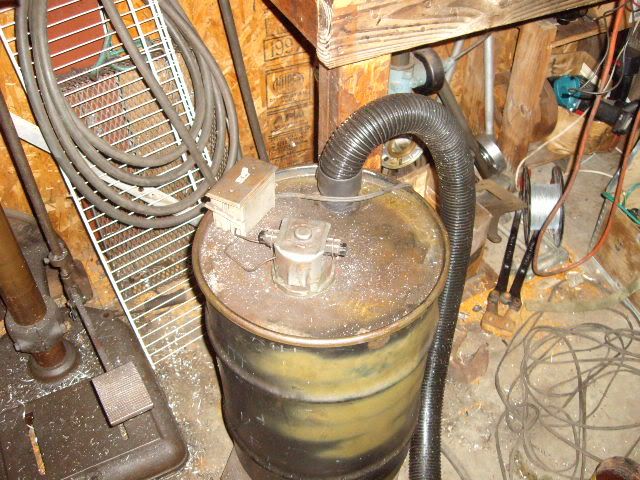
Hi all, well, I had to put her back together and test her, but she was still smoking, and still refusing to pick up any swarf.


together again


after testing, still smoking, no swarf.
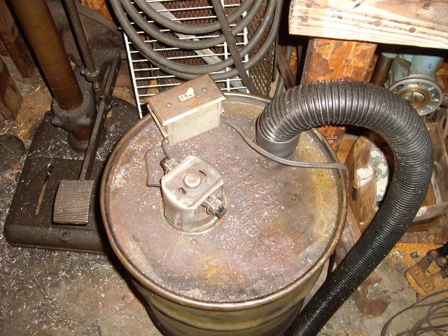
 I had a conference with "the boys", and some of them, knowing bertha was around long before they were, thought she ought to at least get a chance at life support, so I dug around, found another motor scrapped out of another vacuum, and pulled out the old one, putting the shop vac on life support.


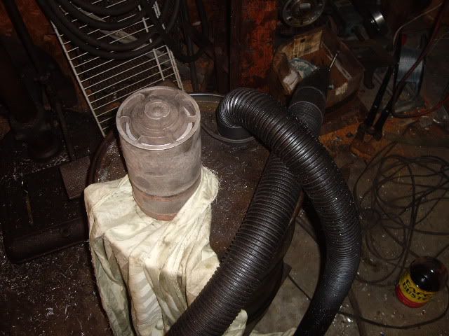
first test, passed with flying colors, she might make it back to the land of the living.  With a temporary filter of a layer of rag, she'll just need a couple of modifications.


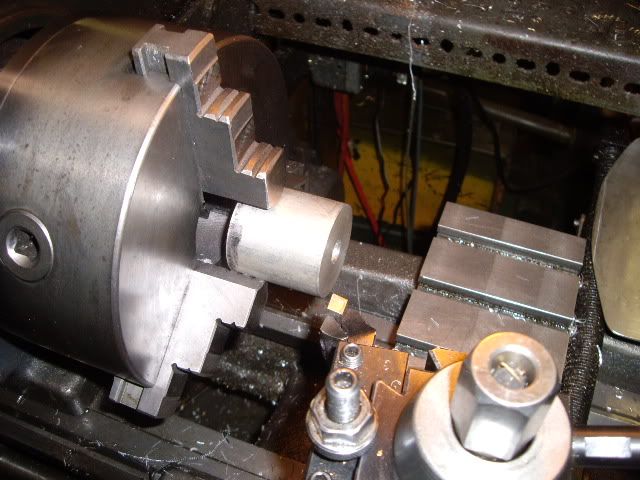
turned a plug to fit in the crank structure, so it'll hold tight in the vise without distortion


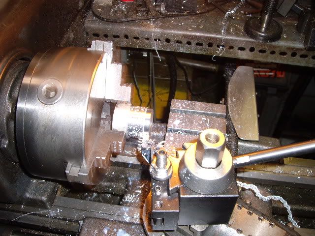
first cuts on the plug


more turning, the blank is inch and three quarters, the bore of the crank support is 1.375


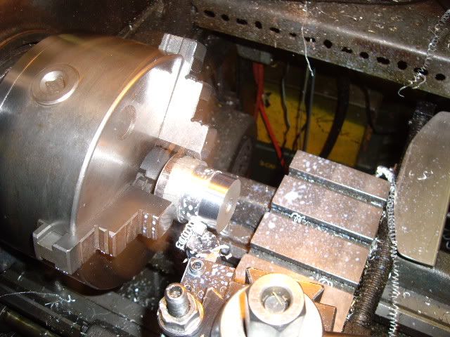
final cuts for size, the support is a very snug fit


Flipped the plug and reduced the o.d. so as not to interfere in the vise


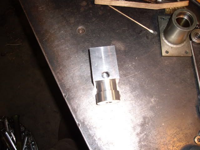
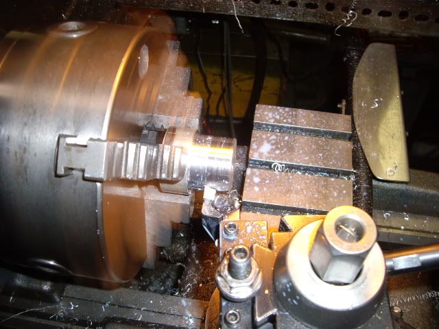
plug in place, should support things just fine


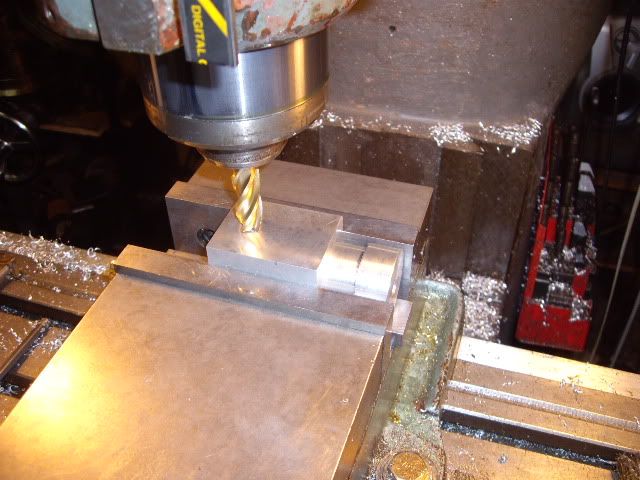
first cuts on the first end face


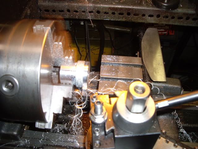
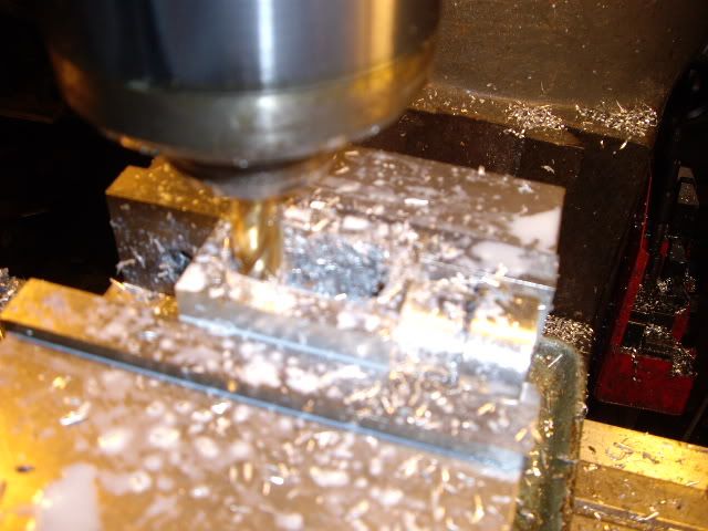
plunge cutting, all the way into the interior with a 9/16ths in end mill


using the end mill, cutting out a rectangular opening


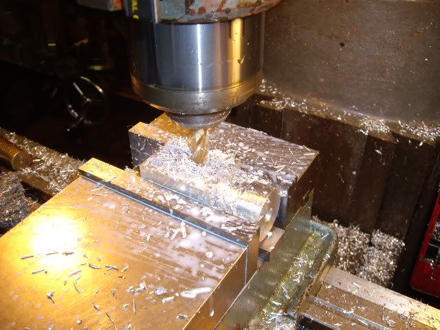
having flipped the support, milling the other end, cutting the rectangular opening


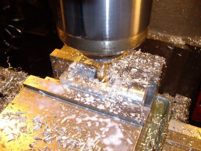
flipped back, final cuts for the first end, opened up fully


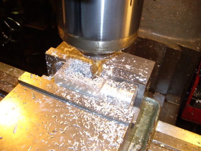
flipped again, final cuts on the second end, fully opened up now.


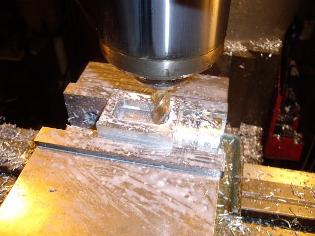
the support, open now, ready to be profiled to shape


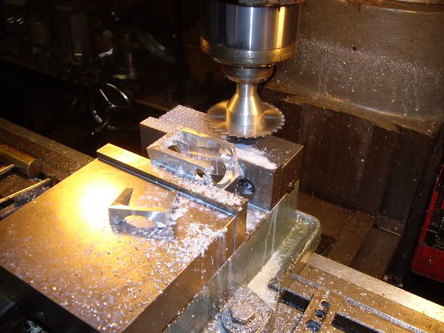
I want to lay out the sides, no special angle, just connecting one point to another, with a gauge so both sides are the same.


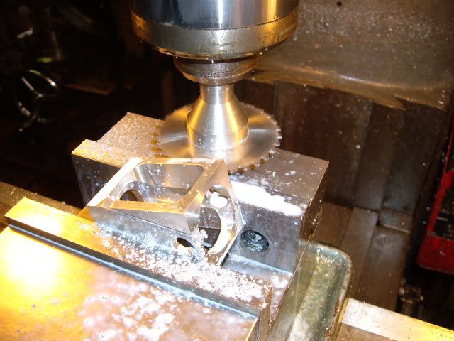
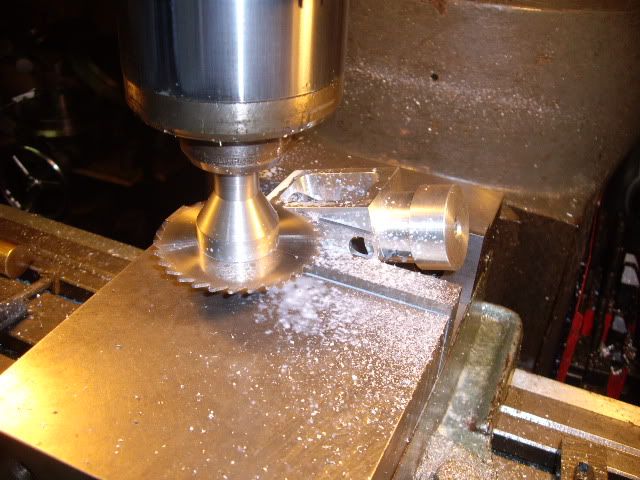
with the angle scribed on both sides, the set up in the mill is by eye, setting the slitting saw right on the line


the slitting saw, .062 thousandths, and the arbor, with a .750 inch shank


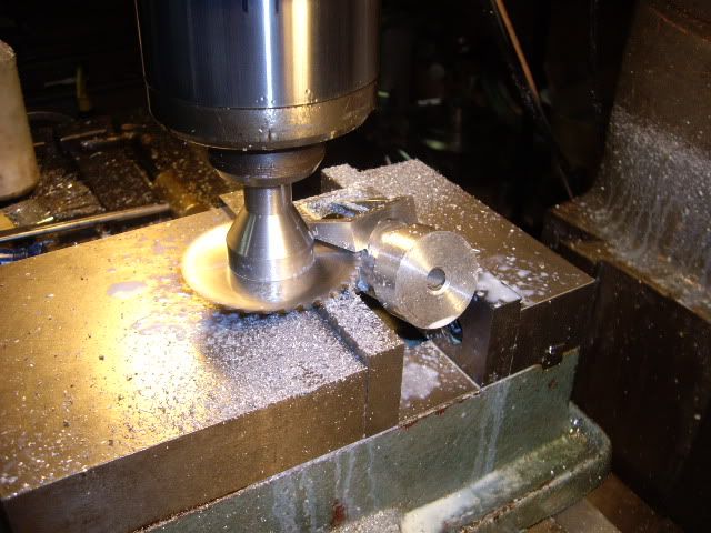
having taken two cuts on the front side, I'm taking a cut on the back side, two to remove the meat, a last one to take out the smallest bit holding the scrap in place


the last cut on the back side, the scrap piece flips onto the vise, just right.


having added the plug again, starting to cut the second side out, no support except the plug for this side.


working the same as the first side, taking the final cut to take off the last piece of scrap


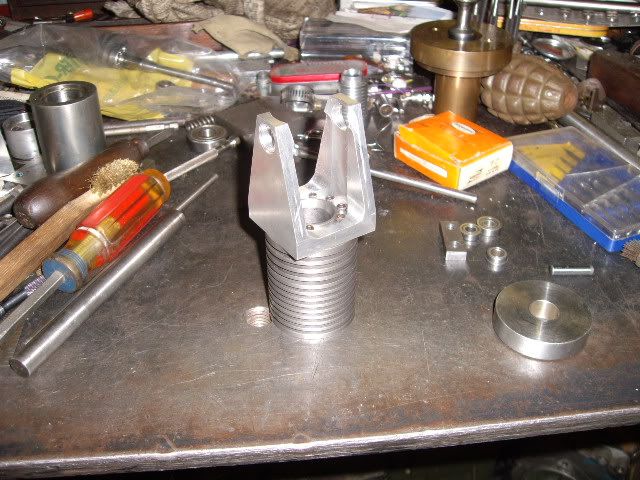
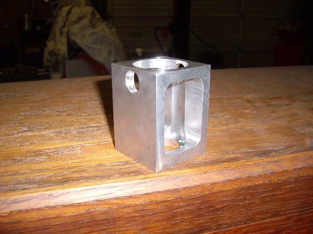
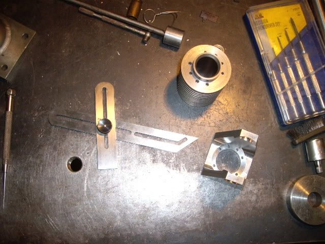
the partially finished crank support, sitting on the cylinder, side view


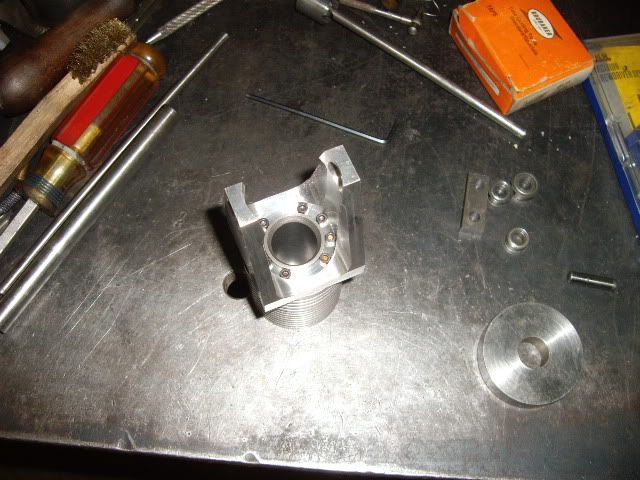
another view, from the top


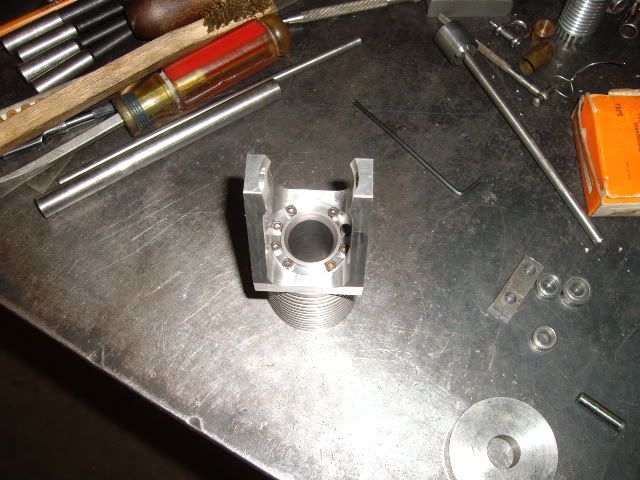
With the crank support bolted in place, you can see the space for the crankshaft to turn in, the next step will be to cut the support in two, so the two sides can have bearings put in place and slid over the mainshafts, then bolted in place to connect with the connecting rod.  Maybe today will bring a crankshaft to a workable state.  I'm still not too sure what the stroke will be, hopefully my guestimate worked out, and an inch and a half, double the bore, will clear the cylinder with the rod, even if I have to beat (forge) it into submission, I mean into shape. :lol: mad jack And remember, only mad dogs and Irishmen go out in the noon day sun :headbang:

Offline NickG

  • Madmodder Committee
  • Hero Member
  • *****
  • Posts: 1890
Re: building a new flame sucker
« Reply #16 on: December 24, 2010, 02:18:45 PM »
Wow, that looks fantastic, some great techniques, sure I can learn from there.

Glad to see the vacuum working again!

Nick
Location: County Durham (North East England)

Offline jim

  • Sr. Member
  • ****
  • Posts: 441
  • Country: 00
Re: building a new flame sucker
« Reply #17 on: December 24, 2010, 04:21:55 PM »
excellent
if i'd thought it through, i'd have never tried it

Offline shoey51

  • Full Member
  • ***
  • Posts: 214
Re: building a new flame sucker
« Reply #18 on: December 24, 2010, 05:28:03 PM »
most excellent :thumbup:

Offline madjackghengis

  • Hero Member
  • *****
  • Posts: 717
  • big engine
Re: building a new flame sucker
« Reply #19 on: December 25, 2010, 07:08:14 AM »
Hi all, thanks for the comments, and the thoughts for my shop vac, does anyone know, is there too big a port for a flame sucker?  I just read in someone else's thread there is such a thing as too small a port, that nice looking piece of stainless with a half inch hole is looking awful good for a head, being round, about the right size, and stainless, just needing some bolt holes and maybe some other work.  I was thinking maybe a half bore sized port, say 3/8ths or so, but a nicely turned piece, kind of hard to ignore. :coffee:  :smart: mad jack

Offline cidrontmg

  • Full Member
  • ***
  • Posts: 229
  • Country: pt
Re: building a new flame sucker
« Reply #20 on: December 25, 2010, 09:09:52 AM »
Lo Jack, I donīt think thereīs any problem in making quite a big port for a flame sucker - as long as you also have a flame to "cover" most or all of the port. So that the engine wonīt suck in any cool air. Thereīs a German chap, H. Midderhoff, who sometimes writes in "Maschinen im Modellbau", who has the ports in his engines as big as the cylinder bore (the cylinder tops are open, with poppet valves, sort of). And they do run!
Hereīs a picture (and a very lousy one at that... taken from a laptop monitor. MiM, 1/2007) of his V6 (inverted) flame sucker. Top right picture shows the 3 cylinders and valves (left is all open, middle closed, right halfway open), and the burners (each cylinder has 2 gas burners). The valves open really wide!
Mr. Midderhoff practically "blows" the flame into the cylinders, instead of relying on the suction only. His motors not only run, but actually develop some power. Lowest right picture is of the engine running.
The port certainly can be too small, so that thereīs no time to fill the cylinder with hot gases.
BTW. Looking real good. What are the materials? Seem like cast iron + steel. 3rd last picture - is that hand grenade live?
 :wave:
« Last Edit: December 25, 2010, 09:23:14 AM by cidrontmg »
Olli
Penafiel
Portugal

Offline madjackghengis

  • Hero Member
  • *****
  • Posts: 717
  • big engine
Re: building a new flame sucker
« Reply #21 on: December 27, 2010, 01:00:56 PM »
Hilo Olli, thanks for the information and the link, sort of.  I suppose if I try and fail, I can always make the port smaller later.  If you have an actual link to that engine, I would sure love to have it.  So far, the cylinder is iron, the piston is steel, the "gudeon" in it for the rod is aluminum, as is the crank structure, and the head will be stainless, because it is not very heat conductive.  I've got a bit more done, four inches of snow means a quiet shop with a nice hot fire in the stove.


turning off the sharp corners of the support, excess metal, and not in keeping with the shape I want.


centering the cylinder under the mill spindle, for head bolt holes, while I've got a square block bolted to the cylinder


drilling ten holes, to match the pattern on the other end, #4-40 is the size


The mill all this is being done on, an 84 Enco with a phase converter making it variable speed in sixteen different ranges


drilling two inch and a quarter by two plus spare, by quarter inch thick crank cheek blanks


reaming the crank pin hole, .250


reaming the main shaft holes, also .250


centering a stub arbor to mount the blanks on, to turn a radius on both ends of the blanks


attaching the blanks with a bolt through both into the stub arbor


starting the turning of the radius, the blanks will be two inches long when done


radius finished, right to size


laying out the crank lines


laying out the second side, both by eye, close enough


setting up the first side in the shaper to cut to finish profile


taking the first cut


still roughing it out


taking shape


getting down to the line


flipped the cutter over for the finish end for the final cuts


another view of the cutting edge


setting up the cross feed, .005 per stroke


last cuts


almost done


the finished side


another view of it (first side)


tool flipped back over, trued up with a stone, set up for the second side


first cuts, ya gotta love the smell of the sulfurated brown cutting oil :thumbup:


more cuts


having finished the second side, I had to go back to the first, to even it up with a roughing cut of  about .030


the final cut on the first side, cheeks fully profiled to shape


deburring after the shaper, with a fine file


and the other side as well


finished up, ready to build up a crank shaft


most of the parts in a pile, yes, that was an enfield bayonet blade you saw, 1918 and still not worn out yet.  That's as far as I got yesterday, we'll see what I can turn out today, still four inches of snow on the ground, and not melting yet, hmmm, even in North Carolina, a special treat that happens only once every few years, maybe ten or so.


Offline cidrontmg

  • Full Member
  • ***
  • Posts: 229
  • Country: pt
Re: building a new flame sucker
« Reply #22 on: December 28, 2010, 05:16:27 AM »
Hi Jack, looking great. Shapers seem very handy, a pity I wonīt ever have one (no room here to even think about getting one).
Thereīs very little in the Net about Mr. Heribert Midderhoff (of the weird flame suckers). No web site, and very few pictures of his work. But heīs a prolific builder, turns out engines like sausages. One picture from a M.E. show in Sinsheim (a big yearly German event):
http://www.modell-dampf-forum.info/Galerie/Sinsheim3/midderhoff2.html

Click on [Voriges Bild], to see the same engine standing still.
Thatīs a 4-cyl version of the same type of cylinder/valve. Heīs also done a 12-cylinder (!) version of it.  Some model builders just are not interested in the Net. Another similarly "challenged" is Mr. Lothar Matrian. If ever you come across that name, itīs worth following. Fantastic work, and no Web presence.
« Last Edit: December 28, 2010, 05:27:36 AM by cidrontmg »
Olli
Penafiel
Portugal

Offline cidrontmg

  • Full Member
  • ***
  • Posts: 229
  • Country: pt
Re: building a new flame sucker
« Reply #23 on: December 28, 2010, 07:41:04 AM »
Just found a picture of Mr. Midderhoffīs 12 cyl. engine. Some guest in the Karlsruhe/Sinsheim 2010 show had it in his album. Air cooled, as you can see. I think it will make quite a racket, with all those 12 valves clicking all the time...    :loco:  But a nice looking and powerful (as flame suckers go) engine.
 :wave:
Olli
Penafiel
Portugal

Offline madjackghengis

  • Hero Member
  • *****
  • Posts: 717
  • big engine
Re: building a new flame sucker
« Reply #24 on: December 28, 2010, 07:59:08 AM »
Lo there Olli, too bad about not fitting a shaper in the shop, they are handy, and while "obsolete", for the home shop, they do all sorts of things that are still better done, one off, on a shaper, than setting up a mill, and the tooling is cheap.  I really appreciate the picture of the 12 cylinder engine, I've got to take a closer look at it, and see what he's up to.  As far as the web, I only learned about it less than a year ago, or I would have been posting for years.  We can always hope Herr Midderhoff gets comfortable with it and starts posting.  Have you been to bettigue.blogspot.com?  That gentleman is a whiz with tiny flame suckers and Stirlings, and has quite a few on u-tube, real fine looking machines, and runners.  My wife has gotten to hate the sound of a flame sucker, I've gone through many stages of pistons, cylinders and valves, trying to find something that will last a while in that little blazer engine, but it isn't a very enduring engine as I've built it so far.  I just replaced the aluminum cylinder and graphite piston with a brass cylinder and bronze piston, because the graphite piston lost compression, I'm not sure if it was piston or cylinder, but it looks like the cylinder is not so round and straight as it seemed on first fire.  Now the brass cylinder and piston are losing compression, I ordered a stick of cast iron last night, and will try a cast iron cylinder and piston, they work together very well, and a bronze valve won't score and wear on the valve face hopefully.  I got a head made for this engine yesterday, and cleaned up the crank support, but won't be able to post till I get back from the doctor's, I've got an infusion, and I.V. for my M.S. in a couple hours, so I have to get ready to go out, and I'm looking at that engine first.  Thanks for all the info and the conversation as it is, quite a thing this forum, isn't it.   :thumbup:  mad jack