Author Topic: Trials and tribulations with a 7x12 lathe  (Read 44610 times)

Offline modeldozer

  • Sr. Member
  • ****
  • Posts: 299
  • Country: es
  • Valencia, Spain
    • AJ´s Truckmodeling
Trials and tribulations with a 7x12 lathe
« on: May 15, 2011, 10:58:16 AM »
Hi to all modders,

My first try at a bit of a post on here, hope this is the correct place to post, it will take a while to finish.

This saga started from brand new.  After the cleanup tried to turn some parts from PVC tubing with poor finish and not taking the same cut in and out.  Investigation revealed the gib plates on the saddle to be LOOSE   :doh:  
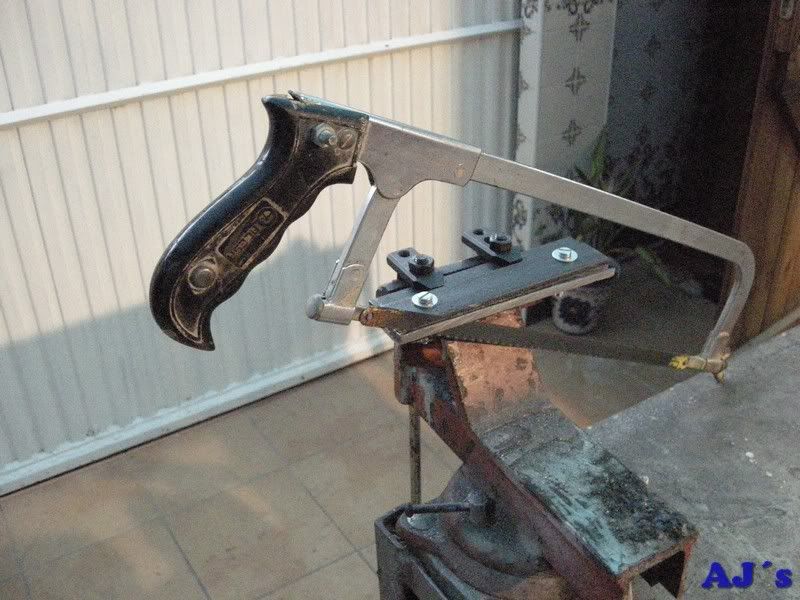
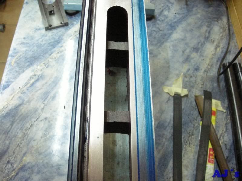
.  Trying to adjust this it was soon apparent that the bed ways was not parallel top to bottom, being a lot thicker at the tailstock end.  This was corrected manually using various oilstones. The gibs were also adjusted with shims rater than the adjusting bolts.  Since then I was able to turn quite a few parts but always had problems with the finish on mild steel and parting off, even plastics.  Then added a Soba vertical slide for milling and had reasonable success milling aluminium.  Recently I tried to do some simple milling in mild steel with a 8mm end mill with disastrous results, mill broke.  Further investigation showed that under force the cross slide lifts up on the right (gib strip) side. Looking into this showed the gib strip to be to small and actually rotating around the adjusting screws.  After a failed attempt to fly cut a new one on the lathe, frustration,  :bang: nearly putting a sledge hammer to the lathe  :hammer:
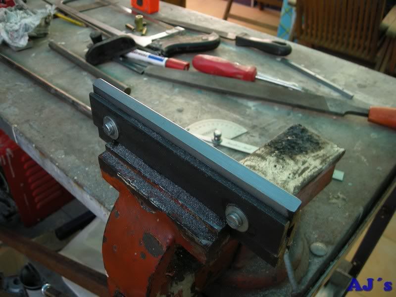
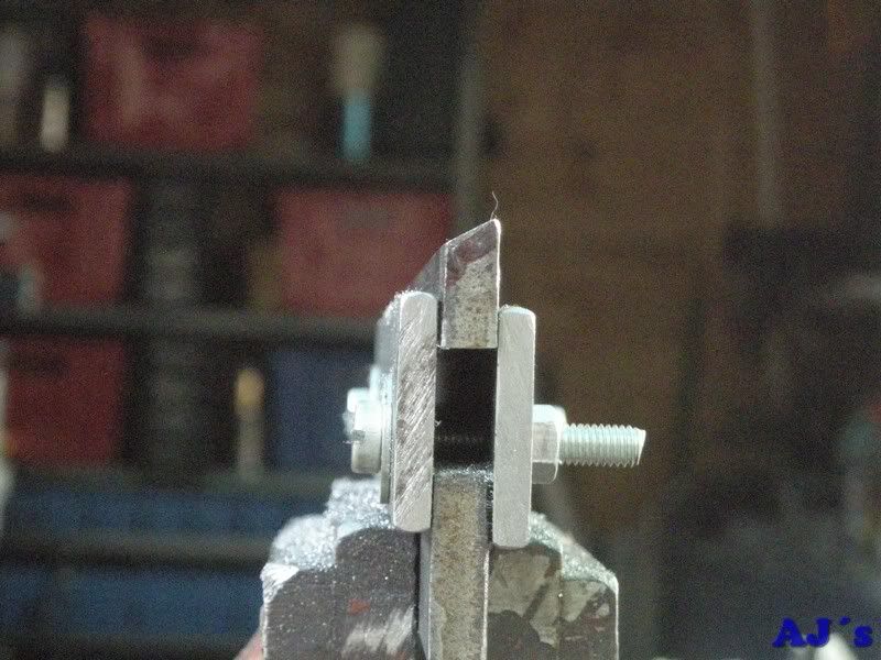
, as a last resort ended up making a new gib strip old school by hand.  This was actually quite fast about 7 hours spread over 2 days.  Here are some pictures of the process. The final surfaces were lapped with W&D on a piece of thick glass.


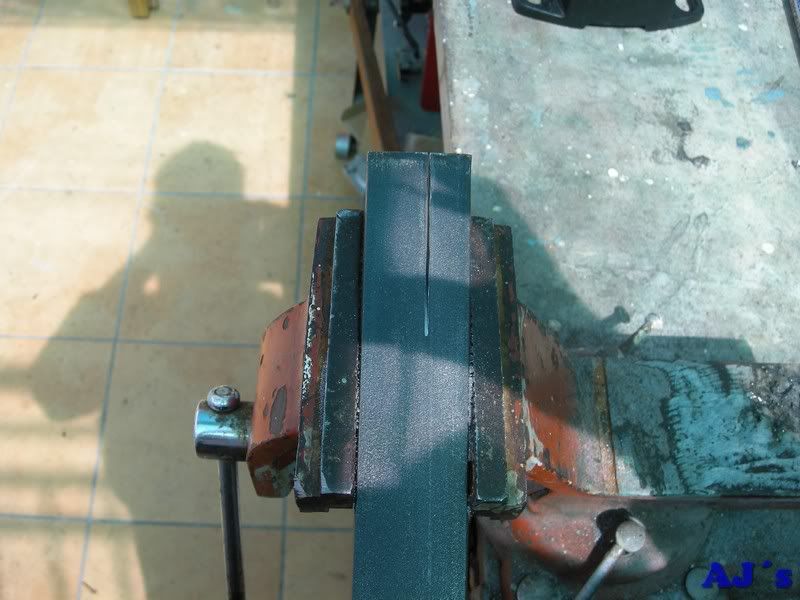
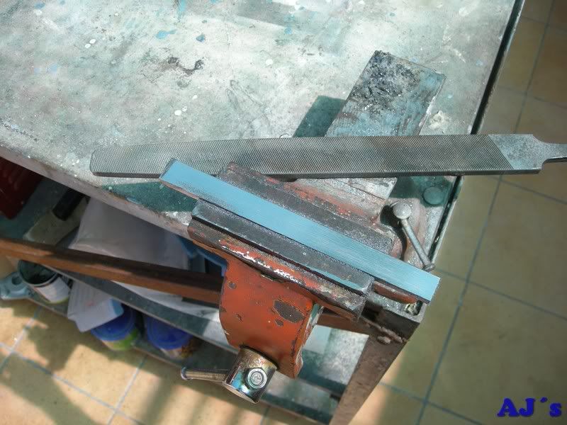
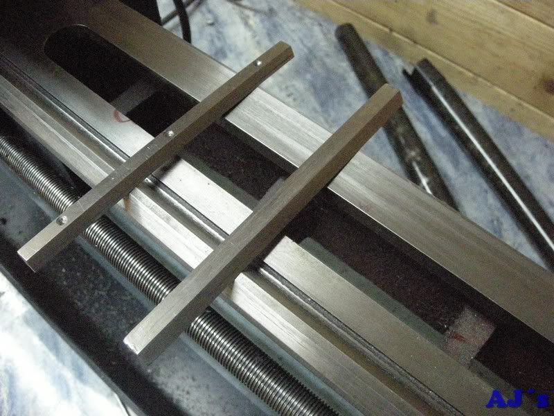
Before cutting to size the gib was used with some W&D to clean the dovetails.

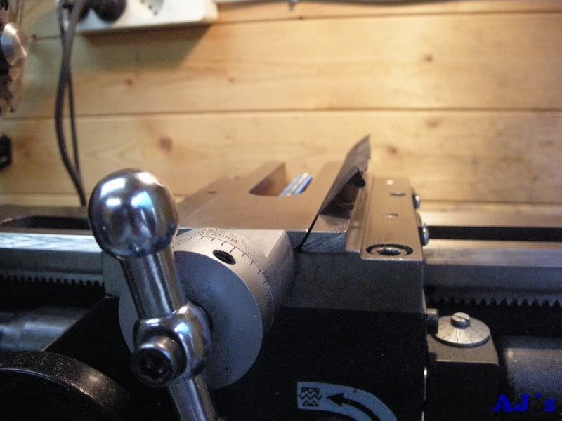
Also noted the saddle has picked up some play, so this was removed and then following methods from here and some other sites on the web the saddle was lapped to the bed ways, testing regularly with mechanics blue.


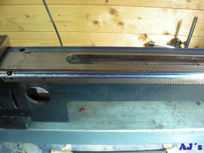
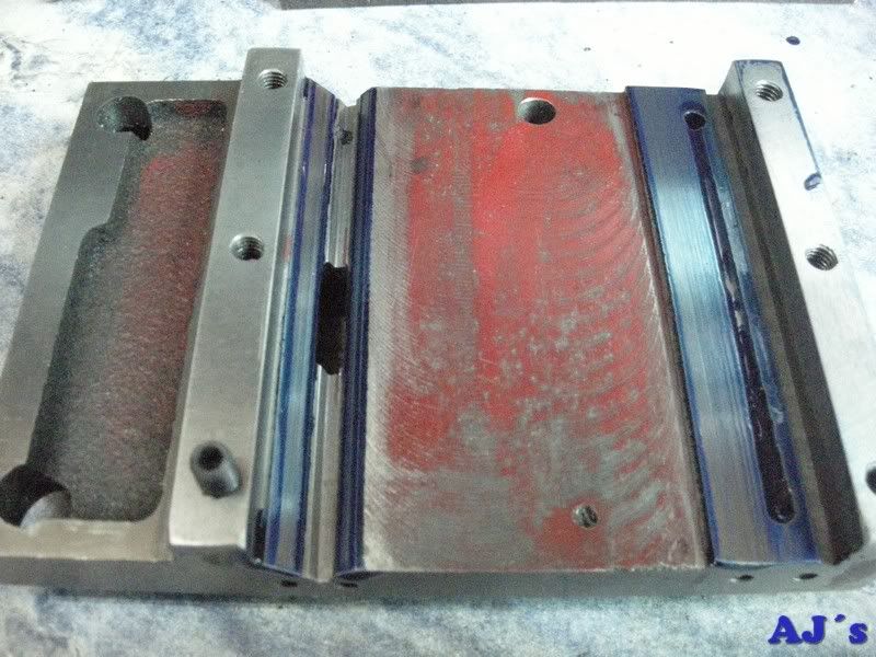
The bed was rechecked wit a micrometer and filed and honed some more for smooth constant fit.


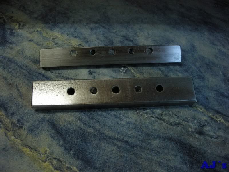
As I do not have a milling machine, new gib pates was hand made from calibrated mild steel flat bar, These are thicker and longer than the originals to add more rigidity. They will also be fastened buy SS studs rater than cap screws. (This is not my idea, seen on the web)


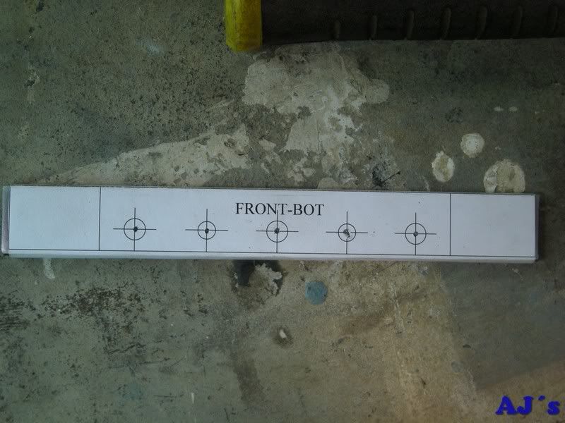
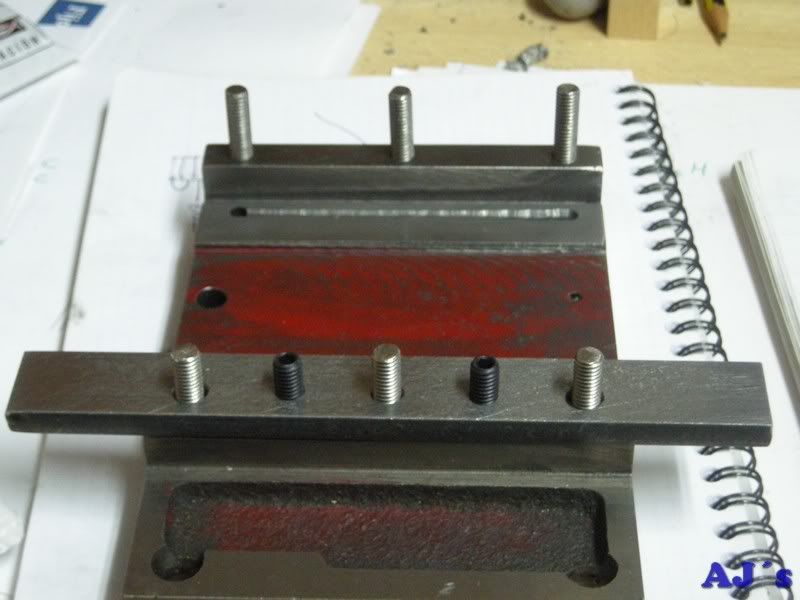
As the bolt holes in the saddle are all over the place a template was drawn to drill them.


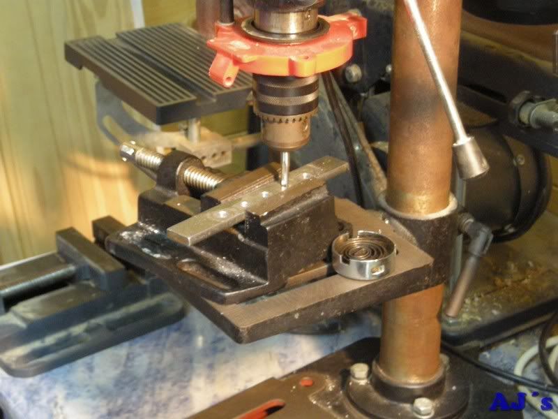
Using the modified drillpress as a tapping stand.

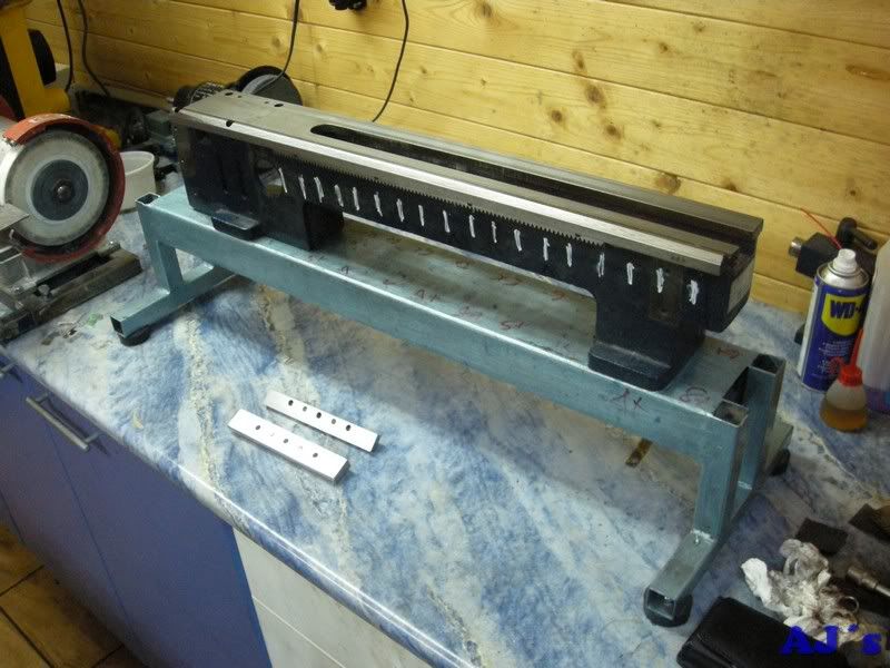
For the mods/repairs to the bed and saddle the lathe was striped down and a nasty surprise found in the headgear.


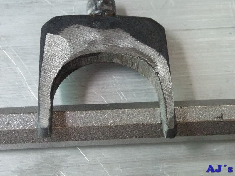
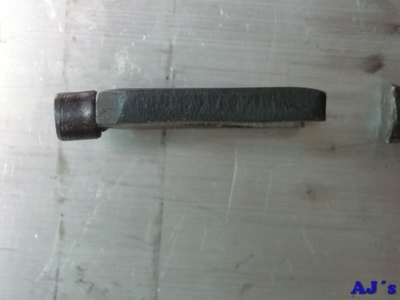
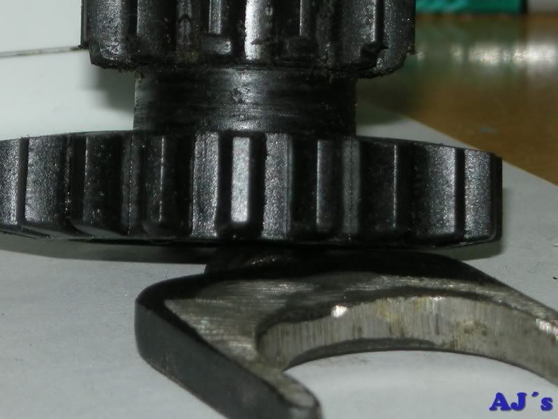
Looks like a gorilla with an angle grinder made the shift fork    :lol:  .  The detents are also no good, causing the damage to the change gear.  This will be looked into later in the rebuild. Hoping to save funds for taper bearings and metal gear.

Next up is refitting the rack to the bed, this will be shimmed for better engagement.  Unfortunately rain, blocked drains and doctor’s appointments will be delaying this a bit.

Offline DaveH

  • Hero Member
  • *****
  • Posts: 1413
  • Country: za
  • Kempton Park, South Africa
Re: Trials and tribulations with a 7x12 lathe
« Reply #1 on: May 15, 2011, 11:42:29 AM »
modeldozer,

You are doing a good job :) The more luv and care you put into it, the more your lathe will give you back :)

Well done :beer:

DaveH
(Ex Leicester, Thurmaston, Ashby De La Zouch.)

Offline loply

  • Sr. Member
  • ****
  • Posts: 260
Re: Trials and tribulations with a 7x12 lathe
« Reply #2 on: May 15, 2011, 01:09:12 PM »
This may be too late, but I went through a similar procedure a few weeks ago and here are some notes for you.


Firstly regarding gibs. I fiddled around with mine quite a bit and in the end I replaced all of them - compound, cross slide and saddle - with a new system wherein I tightened the gib down onto a pile of shim stock material. For the cross slide and compound gibs I attached M4 studs into the gib, and the studs subsequently have a nut popped on them and tightened to squish them flat against the shim stock. This works much better than trying to push the gib out and allows repeatable accuracy down to the thinnest shim you've got - in my case 0.01mm.

By this means I was able to achieve a cross slide which has absolutely no wobble in it - not even a hundredth of a mill - yet slides back and forward with complete ease.

Unfortunately the compound has proved more difficult due to the small surface area, but is acceptable.

I also found the gear selector had been wearing on the gears and have since adopted a technique of changing gear ratios then reversing the lever a bit to put the selector in free space, instead of rubbing against a gear. I did also round the edges over quite a bit.

Lastly headstock mods - I replaced bearings with tapered roller bearings and changed the pulley ratios to reduce the low gear top speed from 1150rpm to 750rpm for an increase in torque. Between these two mods the lathe changed and I was able to achieve more or less mirror finish on mild steel with no 'lines' showing on the work piece.


In conclusion I would highly recommend using shims for your various gibs and if you want a good finish would suggest the motor speed + tapered bearings mods.

Offline andyf

  • In Memoriam
  • Hero Member
  • *****
  • Posts: 1795
  • Country: gb
    • The Warco WM180 Lathe - Modifications
Re: Trials and tribulations with a 7x12 lathe
« Reply #3 on: May 15, 2011, 02:04:52 PM »
Modeldozer,

Despite having no personal experience of Sieg or Real Bull mini-lathes (yours being the latter, I think), I am for some reason  :scratch: a moderator of the Yahoo 7x12 minilathe group.There, some say it's better to keep the original headstock gears, to act as a plastic fuse if a tool crash demonstrates that chuck jaws are hard to machine. And others say that metal gears are noisier.

I'm not advocating that you stick to plastic, but these are points which you might take into consideration.

Andy
Sale, Cheshire
I've cut the end off it twice, but it's still too short

Offline websterz

  • Sr. Member
  • ****
  • Posts: 415
Re: Trials and tribulations with a 7x12 lathe
« Reply #4 on: May 15, 2011, 02:07:19 PM »
This may be too late, but I went through a similar procedure a few weeks ago and here are some notes for you.


Firstly regarding gibs. I fiddled around with mine quite a bit and in the end I replaced all of them - compound, cross slide and saddle - with a new system wherein I tightened the gib down onto a pile of shim stock material. For the cross slide and compound gibs I attached M4 studs into the gib, and the studs subsequently have a nut popped on them and tightened to squish them flat against the shim stock. This works much better than trying to push the gib out and allows repeatable accuracy down to the thinnest shim you've got - in my case 0.01mm.

By this means I was able to achieve a cross slide which has absolutely no wobble in it - not even a hundredth of a mill - yet slides back and forward with complete ease.

Unfortunately the compound has proved more difficult due to the small surface area, but is acceptable.

I also found the gear selector had been wearing on the gears and have since adopted a technique of changing gear ratios then reversing the lever a bit to put the selector in free space, instead of rubbing against a gear. I did also round the edges over quite a bit.

Lastly headstock mods - I replaced bearings with tapered roller bearings and changed the pulley ratios to reduce the low gear top speed from 1150rpm to 750rpm for an increase in torque. Between these two mods the lathe changed and I was able to achieve more or less mirror finish on mild steel with no 'lines' showing on the work piece.


In conclusion I would highly recommend using shims for your various gibs and if you want a good finish would suggest the motor speed + tapered bearings mods.

Can you give us a little more info about the torque improvements you made? I am getting ready to do a top to bottom rebuild of my 7x12 headstock...metal gears, tapered roller bearings, might as well add as much to the job as I can while I'm at it.  :proj:
"In the 60's, people took acid to make the world weird.  Now the world is weird and people take Prozac to make it normal."
 :med:

Offline websterz

  • Sr. Member
  • ****
  • Posts: 415
Re: Trials and tribulations with a 7x12 lathe
« Reply #5 on: May 15, 2011, 02:09:40 PM »
Modeldozer,

Despite having no personal experience of Sieg or Real Bull mini-lathes (yours being the latter, I think), I am for some reason  :scratch: a moderator of the Yahoo 7x12 minilathe group.There, some say it's better to keep the original headstock gears, to act as a plastic fuse if a tool crash demonstrates that chuck jaws are hard to machine. And others say that metal gears are noisier.

I'm not advocating that you stick to plastic, but these are points which you might take into consideration.

Andy

I will be replacing the spindle gears with metal but leaving the plastic change gear in place as the weak link. It will be much easier to replace than the others in the event of a catastrophic work interruption.
"In the 60's, people took acid to make the world weird.  Now the world is weird and people take Prozac to make it normal."
 :med:

Offline modeldozer

  • Sr. Member
  • ****
  • Posts: 299
  • Country: es
  • Valencia, Spain
    • AJ´s Truckmodeling
Re: Trials and tribulations with a 7x12 lathe
« Reply #6 on: May 15, 2011, 03:48:56 PM »
Hi to all,

Thnks for the encoragements and info.

The saddle gibs will be shimed again, the adjusting screws were only added to aid adjustment wile lapping.

Andyf,   Thanks for the tip on the dovetail gibs, will be looking into that one.

On the gears I will only put a metal one on the spindle and retain the plasitc one for the layshaft.  Whwt puley ratio did you use and wher did you get the puleys?  My plan was to add a jackshaft reducer as others have, but changing the current ratio sounds a lot easyer.

Abraham


Offline andyf

  • In Memoriam
  • Hero Member
  • *****
  • Posts: 1795
  • Country: gb
    • The Warco WM180 Lathe - Modifications
Re: Trials and tribulations with a 7x12 lathe
« Reply #7 on: May 15, 2011, 06:23:10 PM »
Hi Abraham,

I think the tip on the dovetail gibs came from Loply, not me.

You probably already know about this source of information:
http://www.toolsandmods.com/mini-lathe-mods.html - look under "Lathe mods and tools". Jose Meneses has a Real Bull like yours. Also look at Marty Nissen's 7x14 Lathe Projects, which are mentioned on Jose's home page. It is a shame that Marty never recorded the end of his project.

Andy


Sale, Cheshire
I've cut the end off it twice, but it's still too short

Offline loply

  • Sr. Member
  • ****
  • Posts: 260
Re: Trials and tribulations with a 7x12 lathe
« Reply #8 on: May 15, 2011, 06:29:40 PM »
I think the original pulleys were something like 14:20, I replaced them with 12:32's which I bought from bearingboys.co.uk.

The ones I bought were a 5mm pitch thereby necessitating a new drive belt too, as the drive belt that came with the lathe was an unusual pitch. I stuck with the original 9mm belt width.

The 32 tooth pulley was the largest one that could fit on the shaft before it would interfere with the spindle.

Both the pulleys are a chippy metal of some kind, machines somewhat similar to CI but isn't. The larger one needed quite a bit of machining as it had flanges and all sorts on it, but I trimmed it up and cut a slot for the wudruff key using a file.

The smaller pulley I didn't bother with the key and just used the cross screw to transfer thrust, seems to work!

As stated in low ratio the top speed has reduced from over 1100rpm to around 750rpm. For me, the critical speeds of about 350-450rpm were lacking in torque previously, resulting in frequent stalling. The change is very noticeable and it VERY rarely stalls now, but perhaps more importantly it maintains the same speed easier, whereas previously even though it didn't stall it would often momentarily slow down during a cut, resulting in inconsistent finish.


Offline modeldozer

  • Sr. Member
  • ****
  • Posts: 299
  • Country: es
  • Valencia, Spain
    • AJ´s Truckmodeling
Re: Trials and tribulations with a 7x12 lathe
« Reply #9 on: May 15, 2011, 07:42:08 PM »
Sorry for the mixup.

Loply,  Thanks for the info, mine tends to hunt below 300RPM and have tried to reajusting the control as per the KB manual to no avail, hence thinking of mechanical reduction.

Andy,  thanks for the links, my mods/repairs is mostly based on toolandmods with some of my own ideas throughn in.

The lathe is sold here in Spain under the Einhell brand and is more compatible to the Real bull than the Sieg.

Abraham
« Last Edit: May 15, 2011, 07:48:15 PM by modeldozer »

Offline cfellows

  • In Memoriam
  • Sr. Member
  • *****
  • Posts: 303
Re: Trials and tribulations with a 7x12 lathe
« Reply #10 on: May 16, 2011, 12:04:46 AM »
I, too, replaced the spindle gear with metal, but left the plastic gear on the countershaft.  I installed tapered gibs on my carriage, but haven't done anything with the gibs on the cross slide.  So far the factory gibs haven't given me any trouble.

Chuck

Offline loply

  • Sr. Member
  • ****
  • Posts: 260
Re: Trials and tribulations with a 7x12 lathe
« Reply #11 on: May 16, 2011, 07:10:34 AM »
Sorry to go off on a tangent but this thread leads me to share an idea I nearly tried.

I'm worried that the increased torque of the new lathe will mean I will break the plastic gears again very shortly.

I was surprised how much work it was to replace those gears and really don't want to do it again!

I designed a new gearbox which used belt drives inside the head instead of plastic gears. Using this method I was able to design a system with 3 speeds instead of just two, using quite wide belts so that they won't ever snap, or at least, shouldn't snap before the belt that goes from the motor to the shaft.

I designed the gearbox similar to a motorbike gearbox - ie with three sets of always-connected belts between the two shafts. The pulleys on the lower shaft are on bearings and are free to rotate, unless a wheel with some studs on it is slid along the shaft whereupon the studs mate with matching holes on the pulley, thereby afixing the pulley to the shaft... If you see what I mean  :coffee:

Because pulleys have a slightly lower 'profile' than gear teeth I was able to make the diameters slightly larger too.

My intention was to end up with 3 ratios - with respective maximum speeds of around 400rpm, 800rpm, 1600rpm.

Using plastic gears it would be senseless to lower the ratio to the point where you could use full motor power at 400rpm as you would almost certainly just break the gear again!

For the moment I haven't bothered but at some point I'd love to do this!

Offline modeldozer

  • Sr. Member
  • ****
  • Posts: 299
  • Country: es
  • Valencia, Spain
    • AJ´s Truckmodeling
Re: Trials and tribulations with a 7x12 lathe
« Reply #12 on: May 16, 2011, 01:51:21 PM »
loply,
  I was thinking of doeing something similar with the jacshaft reducer and leaving the headgear locked in low.  For the torque involved was thinking all metal gears in the head and a "fuse" pulley in the drive to the head, somewhere where it will be easy to replace.

Mannaged to get some of the other tasks done so had a few hours in the shed this afternoon, din not get a lot done so no pitures today.  More time programed for tommorw.

Abraham.

Offline loply

  • Sr. Member
  • ****
  • Posts: 260
Re: Trials and tribulations with a 7x12 lathe
« Reply #13 on: May 17, 2011, 06:20:36 PM »
Abraham,

Well just for your interest here is a video I made tonight whilst experimenting with my lathe. I have just finished the headstock upgrades and this is really the first turning I've done.

This video shows me removing 4mm from the diameter of a steel bar in one pass using hand feed, of note is that on the withdrawal of the tool there is NO secondary cutting what so ever, and what may sound like chatter is the tool chattering against the workpiece due to hand feed.

The end finish was pretty good too! Cut was made with a sharp carbide tool so it was a 'liney' finish but pretty damn smooth and extremely consistent. Motor running at full power which was 750rpm in low gear with the modified pulleys.

Also on that note, I have a set of cheap brazed carbide tools. I discovered tonight they are all crap. I reground them to new shapes and angles on my bench grinder and made a BIG difference. Prior to this there was no way I could remove 4mm at a time, in fact it was always hit and miss whether they would cut at all. I found most of them rubbed on the workpiece no matter what as they didn't have enough relief.


The video actually makes the finish look bad so here's a better pic.


The tit on the end of the part is 0.5mm diameter. At one point I turned a 0.5mm piece about 1cm long but then snapped it.

Prior to the upgrades (headstock bearings, motor speed reduced, modified gibs) the machine chattered like crazy and required several 'spring cuts' if you made a 1mm cutt, and it would stall occasionally and generally be dramatic. I usually stuck to removing 0.35-0.4mm from each side of a part max.

I'm totally confident that I could remove from the diameter 5mm or maybe even 6mm now...

Anyway, what I mean is that I would definitely upgrade the bearings and slow the motor speed down! You won't regret it :)

Offline modeldozer

  • Sr. Member
  • ****
  • Posts: 299
  • Country: es
  • Valencia, Spain
    • AJ´s Truckmodeling
Re: Trials and tribulations with a 7x12 lathe
« Reply #14 on: May 17, 2011, 07:28:38 PM »
Loply,

Many thanks for the info and encoragement.

Spent most of thr day working on the lathe (post to follow soon), but am having problems with the saddle, no matter how tight i adjust the gibs the saddle can be turned/pivoted left to right by 0.02mm (holdig it front and back and foring in opposite directions). Do not know if this is to much,. if so, it seems I might have to get it remachined or replaced.  GRRRR :bang:

Abraham

Offline loply

  • Sr. Member
  • ****
  • Posts: 260
Re: Trials and tribulations with a 7x12 lathe
« Reply #15 on: May 18, 2011, 04:40:35 AM »
I've got the same problem with my saddle!

Will be interested to know how you get on fixing it.

My gib strip on the side of the 'vee' is not as tight as the opposite one, because I was led to believe it was less critical, but I believe this may be causing the rotation.

I note that if I push the saddle down above the vee that the rotation seems to become impossible.

Are you saying that even with really tight gibs you can still rotate it though?

Offline modeldozer

  • Sr. Member
  • ****
  • Posts: 299
  • Country: es
  • Valencia, Spain
    • AJ´s Truckmodeling
Re: Trials and tribulations with a 7x12 lathe
« Reply #16 on: May 18, 2011, 07:09:33 AM »
Yes, even so tight it can not move it has 0.01mm rotation, this is why I think the V in the saddle might need a remachine.

Offline andyf

  • In Memoriam
  • Hero Member
  • *****
  • Posts: 1795
  • Country: gb
    • The Warco WM180 Lathe - Modifications
Re: Trials and tribulations with a 7x12 lathe
« Reply #17 on: May 18, 2011, 08:32:03 AM »
You may find some help on sorting out the Vee both here http://www.toolsandmods.com/saddle.html and on the link it gives to Marty Nissen's work.

Andy
Sale, Cheshire
I've cut the end off it twice, but it's still too short

Offline loply

  • Sr. Member
  • ****
  • Posts: 260
Re: Trials and tribulations with a 7x12 lathe
« Reply #18 on: May 18, 2011, 10:33:36 AM »
Provided the angle of the V is precisely 90, I can't see how it should end up rotating?

Because it's a V it clearly can't be oversized or undersized, and I can't imagine the sides of the V not being parallel?

I agree that lapping it is probably the solution but would be interested to know exactly what the problem is.

Offline modeldozer

  • Sr. Member
  • ****
  • Posts: 299
  • Country: es
  • Valencia, Spain
    • AJ´s Truckmodeling
Re: Trials and tribulations with a 7x12 lathe
« Reply #19 on: May 18, 2011, 04:28:50 PM »
Hi again to all,

Andy and Loply, The saddle have been lapped is as Jose at toolandmods decribes.  Conclutions at this tine is at the end of this post.

A bit more progress.

Made a “shim” for the rack from some 1mm sheet.


Filed a recess for the pinion in the front gib.


Shortened a grub screw to fit under the pinion.


Made a new full chip guard for the apron gears. Also made a thrust washer to prevent the gear eating into the guard.


All fitted.


The saddle was then adjusted for a slightly dragging fit and play checked with a DI.  Up/down with oil on the ways 0.0000 but then found the rotational play mentioned before.


Today only had little time in the shed and the saddle contact with the ways was rechecked with mechanics blue, both sides on the “V” have full contact over the complete with of the saddle, so I am thinking the play is just inherent (Not ridgit enough) of the design.  Will continue on for the moment and see how this affects turning.

All for now

Abraham

Offline modeldozer

  • Sr. Member
  • ****
  • Posts: 299
  • Country: es
  • Valencia, Spain
    • AJ´s Truckmodeling
Re: Trials and tribulations with a 7x12 lathe
« Reply #20 on: May 19, 2011, 03:32:56 PM »
Hi all,

Spent some time today to invetigate the play, me thinks me found it.  As I had to lap the saddle quite a bit to get good contact the "v" in the saddle ended up wider at the edges than in the middle, an unfortunate side effect of lapping the actual guiding surface while using the same to guide.

For cost comparrison have been in contact with Amadeal and at the cost of a new saddle and having no mill myself I think it might be time to bite the bullet and get a new saddle.

Meantime am racking the grey matter   :scratch: to come up with an external guiding system for the lapping process.
Any sugestions welcome.

Abraham

lordedmond

  • Guest
Re: Trials and tribulations with a 7x12 lathe
« Reply #21 on: May 19, 2011, 03:48:28 PM »
the saddle should be scraped to a known prism and camel back , not lapped with wet and dry stuck on.

have you checked the squareness of the saddle to the single axis


BTW you are using far to much blue it should only be the faintest smear and the saddle only moved a few mm not slid the entire length


Offline modeldozer

  • Sr. Member
  • ****
  • Posts: 299
  • Country: es
  • Valencia, Spain
    • AJ´s Truckmodeling
Re: Trials and tribulations with a 7x12 lathe
« Reply #22 on: May 19, 2011, 06:28:12 PM »
lordedmond,

Thank you for the advise.  Unfotuanatly scraping is out of my capabilities due to my disability.  Out of interest though what is a camel back?  Using only very litle blue I found out today trying to detect the problem, learning as I go along (only used it before for setting tooth contact in differentials).

Abraham

lordedmond

  • Guest
Re: Trials and tribulations with a 7x12 lathe
« Reply #23 on: May 20, 2011, 02:41:49 AM »
A camel back is a long straight edge
http://www.schsm.org/SCRAPING.pdf

the blue should only be just discernible on the master part ( non worked bit ) degrease both parts apply blue and wipe 99% off to get an evan smear the lower the worked part on vertically ,then move it a few mm lift off vertically .
your pic show that you have run it end to end and the blue has been shoved off the end , more like a coat of grease ,remember very little and move a little
incidentally you do the ways on the bed with a camel back  then you fit the saddle to the ways, not the other way round , if there are dove tails then you use a prism 


well I need wheels and I can still use a scraper but I was trained when I was an apprentice Large old DC motors ( 100 hp plus ) had brass/babbit bearing but hey that was when I was 15 now 65

good luck with the refurb , IMHO with the cheaper end of machine tool its best to work round the problems as the cast iron is very soft and nearly could be remove with a dumb nail


don't get me wrong I had a 7 x12 it lasted a week ( dangerous electronics , it started up on its own and motored against a hand push ) now my lathe is £10k not touched at all just lube it and USE it to make loco's etc


Stuart

Offline loply

  • Sr. Member
  • ****
  • Posts: 260
Re: Trials and tribulations with a 7x12 lathe
« Reply #24 on: May 20, 2011, 06:13:06 AM »
Abraham,

I'm not sure if I understand how it ended up wider at the edges than in the middle - though I can see exactly why that would cause rotation.

Since mine is the same and I have not (really) tried to lap the saddle to the ways, I wonder they tend to be like that from the factory. If it was milled on a pretty poor mill the bit could flex inwards as it makes the cut, thus resulting in the V being wide at the edges and narrower in the middle?

Maybe you didn't make it like that, maybe you need to lap it some more in order to fix it?

I am almost tempted to buy a or make a precision V and bond it in there to replace the original. If only I could get a precision V which was only 1 or 2 mm thick, and a matching flat piece to jack up the opposite side, which could do with more contact area anyway.


Offline modeldozer

  • Sr. Member
  • ****
  • Posts: 299
  • Country: es
  • Valencia, Spain
    • AJ´s Truckmodeling
Re: Trials and tribulations with a 7x12 lathe
« Reply #25 on: May 20, 2011, 07:54:23 AM »
Thanks fo the replies guys,

Stuart,

Thanks for the link, back as an aprentice we called it a standart for some reason.  Unfortuanatly mine is not that forgiving having lost 90% vision.  As is to "read" the blue have to use electronic visual aids. But keep soldering on finding differt solutions to do things.

Loply,

The Saddle originaly had good contact on the edges, only a verry narrow line at the deepest end (very top of the bedway.  The problem with lapping is as one moves up and down the bed nothing realy prevents the saddle to twist in different directons, progessivly widening the outer edges.  In hindsight should have thought this through better before doing it.

At the moment am trying a few things before going for a repacement.

Abraham

Offline loply

  • Sr. Member
  • ****
  • Posts: 260
Re: Trials and tribulations with a 7x12 lathe
« Reply #26 on: May 23, 2011, 11:40:10 AM »
Hi Abraham,

Just FYI I had a fiddle with my lathe last night.

I discovered that the fit of the gibs on the front of the saddle was not very tight, using a DTI and applying quite heavy finger pressure I could lift the saddle up about 0.03mm on one side and about 0.06mm on the other side.

I adjusted the shims bit when it comes to these tolerances despite the shimstock being 0.01mm I generally found that it would seize up if I removed any - certainly removing the amount of shimstock equal to the free play wouldn't work.

My approach was to remove enough shim so that the saddle just squeezed onto the bed, but could scarcely be moved more than a few inches.

I then used a piece of flat brass with 600, 800 and 1200 grit wet and dry to remove material from the bottom of the bed until the saddle did slide on.

By this means I was able to achieve a fit which was not possible simply by adding or removing shims, as the sanding can reliably and consistently remove a given amount of material, and can be adjusted by area according to tight spots.

I now have the saddle with free play of about 0.02mm and 0.03mm when pushed quite hard with a finger, and this has resulted in around 0.02mm of rotation tangential to the ways when pushed quite hard with fingers.

The rotation and free play does not come with any accompanying sound and feels like flex rather than anything else, ie I feel like something is bending rather than rocking around in free space.

All in all I'm pretty happy with this, I got more or less chatter free cuts of up to 2mm in mild steel prior to this, and I'm sure it will be fine from now on.

Cheers
Rich

Offline modeldozer

  • Sr. Member
  • ****
  • Posts: 299
  • Country: es
  • Valencia, Spain
    • AJ´s Truckmodeling
Re: Trials and tribulations with a 7x12 lathe
« Reply #27 on: May 23, 2011, 06:22:36 PM »
Rich,   Thanks for the feedback. A question if I may, where can I get some 0.01mm shim stock?  Had to use various thicknesses of paper as I don´t have anything that thin.  Have looked on the web but thinnest I found is 0.05mm.

After spending the weeked filing,sanding,fiddeling,,,, I am now at final adjustments.  Am also between shim sizes so am also tweeking the bottom of the bedways.  Had to hand file and sand the gib mounting surfaces of the saddle to get them parallel to the bed (0.04mm difference left to right), surprisingly got them to within 0.01mm.

At the moment (only front adjusted) I have no detectable play up/down but still get 0.02mm "rotational", and think my orriginal conclution of flex/deformation somewhere was correct. It would be interesting to know the measurements of some of the bigger heavier lathes for comparrison. BTW the adjustments and readings were done wth oil on the ways and I have a nice slightly dragging, but smooth slide.

The final verdict will come when some test pieces can be cut. (Don´t know if after all the fiddeling it slill cuts square)

Have also ordered some bits for some of the mods.

Abraham

lordedmond

  • Guest
Re: Trials and tribulations with a 7x12 lathe
« Reply #28 on: May 25, 2011, 06:59:05 AM »
to answer your question


my Myford coni big bore ( £ 10k worth ) tested at the rear of the cross slide 250mm from the centre of the bed i.e. point of rotation in is 0.005mm that is after two years use with no adjustment from me , i.e. as supplied form Myford ( only 5 miles away  :) )

so there you go mind you my cross slide is nearly the length of your bed width wise


Stuart 

Offline modeldozer

  • Sr. Member
  • ****
  • Posts: 299
  • Country: es
  • Valencia, Spain
    • AJ´s Truckmodeling
Re: Trials and tribulations with a 7x12 lathe
« Reply #29 on: May 25, 2011, 10:17:01 AM »
Stuart,

Thank you for the info. I expected it to be a lot less.  The narrow bed and short cross slide was always a bit of a concern to me.  The other concern is there is not a lot of material on top of the "V" in the saddle and it might be speading under force.

For the moment am finishin the rebuid so I can do some test pieces.

Abraham

Offline modeldozer

  • Sr. Member
  • ****
  • Posts: 299
  • Country: es
  • Valencia, Spain
    • AJ´s Truckmodeling
Re: Trials and tribulations with a 7x12 lathe
« Reply #30 on: May 25, 2011, 03:51:57 PM »
Hi to all form a very happy modder  :) :D :ddb:.

After making lots of shims, sanding and tweeking it is all adjusted and working nicely.  Up/down play at all 4 corners less than 0.01mm and ....... the rotational down to just under 0.01mm ( do not have anything that measures finer)

I would like to take a moment to thank everybody for their advice, information and support, without witch I most probably would have given up long ago.  So to all have a few on me  :beer: :beer: :beer: :beer:.

And  :mmr:

More to follow soon.
Abraham

Offline loply

  • Sr. Member
  • ****
  • Posts: 260
Re: Trials and tribulations with a 7x12 lathe
« Reply #31 on: May 26, 2011, 05:53:05 AM »
Morning Abraham,

Probably a bit late now but I got my shim stock just off eBay somewhere - just searched for 'brass shim' or something.

Congrats on finishing the tine tuning, certainly sounds like it ought to be smooth as hell now.

May I ask how you managed to measure the slant on the saddle gib? And how did you manage to sand the saddle flat with accuracy?

Offline modeldozer

  • Sr. Member
  • ****
  • Posts: 299
  • Country: es
  • Valencia, Spain
    • AJ´s Truckmodeling
Re: Trials and tribulations with a 7x12 lathe
« Reply #32 on: May 26, 2011, 06:25:48 AM »
Hi Rich,

Had to do a bit of   :scratch:, I will try to explain.
First measured from the top side surface to the bottom faces where the gibs mount at all 4 corners then at the back between same top surface and the rear flat sliding surface at the bottom, at the front i used a 6mm guide rod from an old printer in the "v" and measured between it and the top, this gave me 8 readings. Then calculate the dfference between the readings for the gib mounts and slide surfaces at each corner, now 4 values. Next i calculated the difference letf/right for the front and the back. Then it was a matter of carefull filing to remove the exess on the high points and finishing on a piece of 360 W&D on my lapping glass.
I will try to do a C-o-C to clear it up if necessary.

Abraham

Offline modeldozer

  • Sr. Member
  • ****
  • Posts: 299
  • Country: es
  • Valencia, Spain
    • AJ´s Truckmodeling
Re: Trials and tribulations with a 7x12 lathe
« Reply #33 on: May 28, 2011, 06:40:35 PM »
Hi all,

Next are some modifications to the lead screw guard supports.  The right hand one had an extension piece to allow for the thread indicator to locate, as I do not use it and will be adding DROs, the extension was removed and the pieces soft soldered with lead free solder (do not have silver soldering equipment).  From the heat when soldered the blackening of the pieces came off.  My only option was to paint the parts.  The left hand one had a piece added to cover the opening on the slanted apron.


Both finished with the template that was used to make the add on piece.


Lead screw installed and some close ups.  The mod on the right extended the travel by some 30mm.


Today made one C-spanner and started the other for the castle nuts on the spindle.


Abraham


Offline Henning

  • Full Member
  • ***
  • Posts: 136
  • Country: no
  • All the kit and no clue!
Re: Trials and tribulations with a 7x12 lathe
« Reply #34 on: May 30, 2011, 09:00:39 AM »
Nice work this far!  :headbang:

I notice you have covered the lead screw. Where did you find the cover? I got one half of a "full size" one the other day and was wondering if i could cut that in two and use that, but i have other things on at the moment so so far it's just sat there on my bench.
Henning

Just because i can't, doesn't mean i shouldn't?
Tool- lover, with a collection to show for it!

Offline modeldozer

  • Sr. Member
  • ****
  • Posts: 299
  • Country: es
  • Valencia, Spain
    • AJ´s Truckmodeling
Re: Trials and tribulations with a 7x12 lathe
« Reply #35 on: May 30, 2011, 12:22:04 PM »
Henning´

They came with the lathe, just modified them slightly.

Offline modeldozer

  • Sr. Member
  • ****
  • Posts: 299
  • Country: es
  • Valencia, Spain
    • AJ´s Truckmodeling
Re: Trials and tribulations with a 7x12 lathe
« Reply #36 on: June 05, 2011, 01:53:07 PM »
Hi to all,

Progress is a bit slow due to rain. :(
The other spanner was finished. Have included some progress pics.


The spindle was then removed from the headgear with a makeshift puller.  Taper bearings and a metal gear were ordered.


Next after lots of measurements the gearshift mechanism was drawn to scale so the correct profile for the shift fork could be determined.  A template was printed and stuck to a 6 x 40mm cold rolled flat bar.  From this the new fork was made.  A template was also used to locate the centre for the shaft piece, the hole has to be offset towards the top.  A hole was drilled and taped M4.


Next a piece of 8mm round bar was squared, the centre found and centre punched.  This was also drilled and tapped M4.  A short grub screw was then used to join the pieces.


A test fit of the new fork was made and all seems to work very well.  Once the lathe is running I will make two spacer sleeves to fit on the lay shaft to prevent the gear from traveling to far.


Abraham

Rob.Wilson

  • Guest
Re: Trials and tribulations with a 7x12 lathe
« Reply #37 on: June 05, 2011, 03:06:46 PM »
Hi Abraham 

Your sure doing a fine thorough job of putting the lathe right  :clap: :clap: :clap: :clap:  ,, i am sure it will be a pleasure to use when finished  :dremel:


Rob  :thumbup:

Offline Stilldrillin

  • Global Moderator
  • Hero Member
  • *****
  • Posts: 4972
  • Country: gb
  • Staveley, Derbyshire. England.
Re: Trials and tribulations with a 7x12 lathe
« Reply #38 on: June 05, 2011, 03:44:43 PM »
Abraham.
I've been quietly watching, until now......  :wave:

Wonderful attention to detail.  :clap: :clap:

The lathe is going to be a cracker, when you've finished!  :thumbup:

David D
David.

Still drilling holes... Sometimes, in the right place!

Still modifying bits of metal... Occasionally, making an improvement!

Offline modeldozer

  • Sr. Member
  • ****
  • Posts: 299
  • Country: es
  • Valencia, Spain
    • AJ´s Truckmodeling
Re: Trials and tribulations with a 7x12 lathe
« Reply #39 on: June 06, 2011, 06:35:43 PM »
Hi Rob and David,  thank you for the encoragement.  It is slow going at the moment as I am wiating on some parts.

Abraham

Offline modeldozer

  • Sr. Member
  • ****
  • Posts: 299
  • Country: es
  • Valencia, Spain
    • AJ´s Truckmodeling
Re: Trials and tribulations with a 7x12 lathe
« Reply #40 on: June 15, 2011, 05:20:49 PM »
Hi to all,

Finally made some more progress.  The spindle assembly was measured and drawn to scale so I could sort out the spacers and bearing covers.  New bearing covers were designed incorporating lip type seals.  As the lathe is out of commission tool paths was programmed to cut the covers on my CNC router.


The parts also arrived and I went in search of some raw materials.  Found a great non-ferros supplier only 20min drive from our home.  One of the other members on here from Spain actually gave me the name of the supplier, they even sell off cuts at reduced rates.   :mmr: 
The mild steel I got from a friend at a large manufacturing plant.


A template was printed and the cover roughed out in a piece of 10mm alu plate.  It was set up on the router using my web cam centre finder.


It was then machined.


After deburring and cleanup with the seal installed.  An added advantage of the cover is it gives more support for the lay shaft bearings.


Next up is cleaning the spindle and reassembly.  The rear cover will be done on the lathe when it is at a usable stage.

Abraham


Offline loply

  • Sr. Member
  • ****
  • Posts: 260
Re: Trials and tribulations with a 7x12 lathe
« Reply #41 on: June 16, 2011, 07:36:42 AM »
Hi Abe,

Looking good! You're probably already aware but another thing to make is a new spacer for the preloading of the bearings on the external rear of the spindle. If your lathe is like mine the original was about 5mm oversized and just spun around like a lunatic when the lathe was ran! (Who on EARTH designed it?!). I made one with a very thick OD so that it contacted the bearing on the largest possible area for even preloading. I had to mill out a gap to allow the key for the gear to sit.

Big suppliers offcut sections are definitely the place to go for materials - I used to buy odds and ends off eBay but it was very poor value - I recently got 60cm of 50mm steel bar (a hefty lump!), and 1.5m of 20mm steel bar, for £10, and he was trying to give me more!

Got about 5 meters of 50x25x5 steel box and two lengths of 30mm and 40mm steel rod for £10 last time too. Can't beat it  :clap:

Offline modeldozer

  • Sr. Member
  • ****
  • Posts: 299
  • Country: es
  • Valencia, Spain
    • AJ´s Truckmodeling
Re: Trials and tribulations with a 7x12 lathe
« Reply #42 on: June 16, 2011, 05:46:22 PM »
Hi Rich,

The spacers are actually the reason I drew the assembly, it just did not make sense to me.  After drawing it all I actually found that with the normal bearings, spacers and gear assembled, the distance between the insides of the two bearings was 2+mm more than the registers in the housing.  With the taper rollers it ends up 0.5mm to short, makes one think.  :scratch:  I will also be making a fatter rear one from mild steel for the rear lip seal to ride on.(still need to get the length once all is in its place)

 :update:
The spacers next to the bearings needed a step cut to clear the cages.  They were machined with the CNC router.


Everything was given a thorough cleanup, there was a lot of casting sand still embedded on the inside surfaces of the housing.  The “hub” on the spindle where the new seal will ride was polished.
All ready for assembly.


It was then all assembled dry and alignments checked.  I took some measurements to make two spacers for the lay shaft to act as stops, preventing over travel of the change gear.
Next I used a method we use in the adjustment of taper bearings in machine transmissions.  Between the gear and last spacer two pieces of soft solder is trapped, the preload is then adjusted and all disassembled. By measuring the thickness of the flattened solder the spacer thickness is determined.


Here it averaged out to 1mm, so I made two 0.5mm ones from alu sheet to go both sides of the gear assm.  Also rounded over the ends of the shift fork to prevent any foul-ups. A small relief was also made in the fork to clear the shift lever shaft.


Hopefully final assembly is next.

Abraham

Offline ozzie46

  • Sr. Member
  • ****
  • Posts: 260
  • Country: us
Re: Trials and tribulations with a 7x12 lathe
« Reply #43 on: June 16, 2011, 07:41:25 PM »


 A very timely thread as I just received the bearings to redo my 7 x 12.

 You're doing a nice job of explaining things.

  Ron

Offline doubleboost

  • Madmodder Committee
  • Hero Member
  • *****
  • Posts: 1619
  • Country: gb
  • Newcastle Upon Tyne
Re: Trials and tribulations with a 7x12 lathe
« Reply #44 on: June 16, 2011, 07:53:35 PM »
This machine will be a credit to you  :clap: :clap: :clap: :clap:
John

Offline andyf

  • In Memoriam
  • Hero Member
  • *****
  • Posts: 1795
  • Country: gb
    • The Warco WM180 Lathe - Modifications
Re: Trials and tribulations with a 7x12 lathe
« Reply #45 on: June 17, 2011, 03:28:27 AM »
If anyone needs the dimensions of the 7x minilathe spindle, Little Machine Shop's drawing is reproduced at http://www.toolsandmods.com/mini-lathe-parts-drawings.html

Andy

Sale, Cheshire
I've cut the end off it twice, but it's still too short

Offline loply

  • Sr. Member
  • ****
  • Posts: 260
Re: Trials and tribulations with a 7x12 lathe
« Reply #46 on: June 17, 2011, 04:45:34 AM »
I believe the original spacers on my spindle were also too small - my replacement bearings were thicker than the originals, yet, I had to make thicker spacers to make them fit with no free play on the gear?

Had me confused for ages, I think it's assembled with the upper gear just loose with a spacer to prevent it moving "too much" but it can move back and forth by a bit. It's quite a tight push fit though.

May explain why they break so easily.

Offline modeldozer

  • Sr. Member
  • ****
  • Posts: 299
  • Country: es
  • Valencia, Spain
    • AJ´s Truckmodeling
Re: Trials and tribulations with a 7x12 lathe
« Reply #47 on: June 17, 2011, 08:19:13 AM »
Thanks guys for the encorragement and link.

Bussy with the assembly, but ran into yet another snag :bang: for some reason once the laysaft is installed the bearings end up so tight it hardly turns.  Lunchtime here so the ivestigation will start later.

Anyone knows where one can find standard press fit data?

Abraham

Offline dsquire

  • In Memoriam
  • Hero Member
  • *****
  • Posts: 2275
  • Country: ca
  • Kitchener, Ontario, Canada
Re: Trials and tribulations with a 7x12 lathe
« Reply #48 on: June 17, 2011, 08:53:15 AM »
modeldozer

I believe that information is in the Machinist Handbook.  :D

Cheers  :beer:

Don
Good, better, best.
Never let it rest,
'til your good is better,
and your better best

Offline modeldozer

  • Sr. Member
  • ****
  • Posts: 299
  • Country: es
  • Valencia, Spain
    • AJ´s Truckmodeling
Re: Trials and tribulations with a 7x12 lathe
« Reply #49 on: June 17, 2011, 06:47:58 PM »
Hi all,

Don, thanks for the reply .

Managed to find the bearing fit data on the SKF website. The lay shaft was 0.01mm oversize causing the bearing inners to expand too much and bind.  Used my pillar drill and some W&D to carefully reduce the diameter.

With the spindle assembled and preloaded I temporarily installed the feed tumbler assembly and main drive to check the length for the rear spacer. Turns out the alignment are good with the current length.


All assembled.


The headgear was then fitted to the bed and the alignment with the bed ways checked.  It has a slight taper both vertical and horizontal (0.04mm over 200mm).  At the moment I am busy adjusting this.


Abraham


Offline cfellows

  • In Memoriam
  • Sr. Member
  • *****
  • Posts: 303
Re: Trials and tribulations with a 7x12 lathe
« Reply #50 on: June 17, 2011, 11:19:55 PM »
So, exactly how are you adjusting the headstock to take out the two tapers?

Thx...
Chuck

Offline modeldozer

  • Sr. Member
  • ****
  • Posts: 299
  • Country: es
  • Valencia, Spain
    • AJ´s Truckmodeling
Re: Trials and tribulations with a 7x12 lathe
« Reply #51 on: June 18, 2011, 04:05:41 AM »
Hi Chuck,

So far only busy with the vertical, and this one is lower at the tailstock end, am shimming under the lefthand of the headstock (front and rear). Am using aluminium foil as shims.  The procedure for testing is known as "Rollies dads method" and is on the toolandmods site.

Abraham

Offline cfellows

  • In Memoriam
  • Sr. Member
  • *****
  • Posts: 303
Re: Trials and tribulations with a 7x12 lathe
« Reply #52 on: June 18, 2011, 12:43:32 PM »
Hi Chuck,

So far only busy with the vertical, and this one is lower at the tailstock end, am shimming under the lefthand of the headstock (front and rear). Am using aluminium foil as shims.  The procedure for testing is known as "Rollies dads method" and is on the toolandmods site.

Abraham

Thanks, Abraham.  I'm familiar with the "Rollies Dad's method", but just wonderered if you shimming or scraping.  I think my lath also has some slight headstock alignment issues.  Hasn't been a problem so far because I do mostly pretty shallow work with it.  But I may have to make adjustments at some point.

Chuck

Offline modeldozer

  • Sr. Member
  • ****
  • Posts: 299
  • Country: es
  • Valencia, Spain
    • AJ´s Truckmodeling
Re: Trials and tribulations with a 7x12 lathe
« Reply #53 on: June 20, 2011, 08:28:39 AM »
Hi all,

Been at aligning the headstock for three days now, aaand just as me thought me had it nicked ... decided to verify it at varios locations along the travel.   The bed is bent badly in the horizontal   :(  From the chuck the first 80mm is good and then in the next 80mm it tapers back 0.1mm.

Two options I can think of now:

Buy an new bed of unkown "straightnes"
or have this one reground, for this i will need to locate a machine shop with the right equipent/experties and most probably expencive. GRRRRRRR. :bang: :bang: :bang:

As a side note, have located a major sorce of non rigidity in the bed, the part where the headsock bolts on is only supported at the front and left side and it litarly bends by just resting a hand on the headstock.  Found this by chance while checking the alignment, Di was moving as I was moving my hand so I investigated a bit and with the DI between the top of the rear foot and the underside of the headstock, with only light pressure on top it deflects 0.02mm.  Will need some invetigation for a cure.

Sad  :( and frutrated  :bang:

Abraham

Offline loply

  • Sr. Member
  • ****
  • Posts: 260
Re: Trials and tribulations with a 7x12 lathe
« Reply #54 on: June 20, 2011, 09:24:13 AM »
Hi Abe,

So are you saying the V in the bed is not straight, causing the saddle to move away/towards the spindle axis at different points?

Could you identify the areas where the bend occurs and simply scrape them flat? If the 'V' is machined with a 'bulge' on one side this would work, else you would end up with a V which is thinner in spots than others, but it may still be fine, you would just loose contact on one side of the V for the duration of that spot - not ideal, but better than a 0.1mm bend!

Alternatively you could scrape the entire V to a thinner shape and remove the bend, but you would end up having to re-fit the saddle quite a lot?

Rich


Offline modeldozer

  • Sr. Member
  • ****
  • Posts: 299
  • Country: es
  • Valencia, Spain
    • AJ´s Truckmodeling
Re: Trials and tribulations with a 7x12 lathe
« Reply #55 on: June 20, 2011, 10:47:16 AM »
Hi Rich,

The V seems to be bent.  Verticaly I have got it perfect (0.00mm on my DI)  Unfortunatly it is to much for scraping, mind you might even be to much for a regrind, like you mentioned it will end up narrower, unless a lot is tacken of the flat surface as well .  Looking into a way of staightening it at the moment  :scratch:

Abraham

PS. Just looked, new bed 142€ shipping included  :scratch:

Offline billmac

  • Jr. Member
  • **
  • Posts: 20
  • Country: gb
Re: Trials and tribulations with a 7x12 lathe
« Reply #56 on: June 20, 2011, 10:51:08 AM »
Abraham -

It is possible that the method you are using to measure headstock alignment is misleading you - for several reasons.

If you use a dial indicator with a standard ball foot to measure vertical alignment as you show in your photograph, you will only get a true reading if you have no (zero) misalignment in the horizontal direction. The reason is that any slight horizontal movement will call the ball to run down the side of the round bar. To avoid this you should get an 'elephants foot' for your indicator. This has a flat base and can tolerate a small amount of movement at 90 degrees and still give a true reading. The same argument applies to horizontal measurement.

The second issue you will have is that you must get a degree of droop in a test bar, just under its own weight. You can calculate this to subtract it from your apparent reading. This may be too small to worry about compared to your other problems. Droop is not an issue when measuring horizontally, provided that you use a flat bottomed foot for your indicator.

The third potential issue is with your test bar itself. It has to be very straight for the tests that you are doing. Ideally a ground bar is needed. you can check this within reasonable limits with a surface plate and vee blocks.

Fourthly, a test that just runs along the top of a test bar assumes that the bar is held straight by the chuck. Ideally I would do away with the chuck and use a test bar fitting in your spindle taper. These are available at a reasonable price. In either case you need to take readings with the bar rotated through 90 degree intervals, to find and eliminate the effect of the chuck and taper not being straight and concentric with the axis of the spindle.

Last, the test can be compromised by the TIR of your spindle bearings. You can remove this effect to some extent, but it could be significant enough to cause apparent problems over the distance that you are clocking your bar.

Can't do much about the flexibility of your lathe bed though :scratch:

Offline modeldozer

  • Sr. Member
  • ****
  • Posts: 299
  • Country: es
  • Valencia, Spain
    • AJ´s Truckmodeling
Re: Trials and tribulations with a 7x12 lathe
« Reply #57 on: June 20, 2011, 11:07:17 AM »
Hi billmac,

Thanks for the info.  To compensate for chuck runout, bar straightness I am using the methot known as "Rollies dads method", with this am basically determining the centre axis of a cam at each point along the bar and comparing these.

Neet to find one of those "elephats feet "

Abraham

Offline modeldozer

  • Sr. Member
  • ****
  • Posts: 299
  • Country: es
  • Valencia, Spain
    • AJ´s Truckmodeling
Re: Trials and tribulations with a 7x12 lathe
« Reply #58 on: June 24, 2011, 07:05:10 PM »
Hi all,

Lathe went in to a major machine shop today.  They will have a look at what can be done an quote on the job. So holding all thubs and praying am hoping for good news.

Abraham

Offline modeldozer

  • Sr. Member
  • ****
  • Posts: 299
  • Country: es
  • Valencia, Spain
    • AJ´s Truckmodeling
Re: Trials and tribulations with a 7x12 lathe
« Reply #59 on: June 27, 2011, 04:43:15 PM »
Hi all,

Ended up going to quite a few machine shops, non could do the job. Finaly found a machine tool vendor repair shop that is willing to do it for 250.00€. Decitions decitions? :scratch:

Saw some beautifull machines while there :drool: :drool: alas all to big for my tiny shed.

10x36 chinese lathe like quite a few modders have aroud 5000€, smallest with power cross feed, can´t remeber the size, 3600€ and my favorite 250x500mm 1400e :drool: :drool:

Abraham