Author Topic: 4x6 Rebuild  (Read 20827 times)

Offline sparky961

  • Hero Member
  • *****
  • Posts: 844
  • Country: ca
4x6 Rebuild
« on: June 18, 2011, 04:25:12 PM »
I've been slowly plugging away at rebuilding a 4x6 bandsaw I picked up for next to nothing.  A good thing too, because there were lots of missing and damaged parts!  Fortunately, the other one I have works fine and I can use it as a model for making new parts.

I put a lot of time and effort into making new blade guides, and I have some pictures of the process that I might post a bit later.  This post is related to the main worm drive, and what I believe to be a bronze gear...


I have a few options here, and I'd be appreciative of input from those who know better than I.  Here's what I'm considering:

1. Purchase a replacement - from where, and how much?
2. Make a replacement - pretty sure I can do a good job of it, but need to consider material and time cost vs. purchasing a replacement.  It seems brass is much easier to come by than bronze.  Would I regret making the gear from brass rather than bronze?

Much thanks!  Bug me if you'd like to see those other pictures and I'll see what I can come up with.

-Sparky

Offline tomrux

  • Jr. Member
  • **
  • Posts: 34
Re: 4x6 Rebuild
« Reply #1 on: June 18, 2011, 06:38:00 PM »
sure as hell looks like steel in the pics mate. does a magnet stick to them at all ??????

know the ones in my unit are steel.


Tom

Offline sparky961

  • Hero Member
  • *****
  • Posts: 844
  • Country: ca
Re: 4x6 Rebuild
« Reply #2 on: June 18, 2011, 06:51:59 PM »
The worm itself is almost certainly steel.  What would the technical name for the other part be - the spur gear?  This is the one that's chewed to almost nothing.

I'll be damned... a neodymium magnet just barely sticks to it!  It's not steel, but maybe this would help to identify what it's made from?  I was thinking bronze because it isn't a red brass and it isn't quite as golden as a yellow brass.  It is, perhaps a bit lighter coloured than I'd expect for bronze though.

Any good tests to tell the difference between brass and bronze?  Is it really going to matter in the end?  Maybe I just make it out of steel and call it a day?

-Sparky

Offline John Stevenson

  • In Memoriam
  • Hero Member
  • *****
  • Posts: 1643
  • Nottingham, England.
Re: 4x6 Rebuild
« Reply #3 on: June 18, 2011, 07:12:25 PM »
They are bronze and there must have been tens of thousands of these made and sold by people like Grizzly and Busy bee that I'm guessing they wouldn't be worth making but buy the part instead.

http://www.busybeetools.com/product_manuals/B013N.pdf

John s.
John Stevenson

Offline Bernd

  • Madmodder Committee
  • Hero Member
  • *****
  • Posts: 3688
  • Country: us
  • 1915 C Cab
    • Kingstone Model Works
Re: 4x6 Rebuild
« Reply #4 on: June 18, 2011, 08:14:05 PM »
I'm with John. It would be better to buy one. Making one is a bit harder than you might realize. Also the worn part is called a "worm wheel" or "worm gear".

Bernd
Route of the Black Diamonds

Offline tomrux

  • Jr. Member
  • **
  • Posts: 34
Re: 4x6 Rebuild
« Reply #5 on: June 18, 2011, 09:45:31 PM »

"magnet just barely sticks to it"


any sort of attraction at all means it is ferous. brass or bronze will not have any attraction. touch it with a dremel grinder, sparks will tell ya.

I'm with the others more hassle than worth. just buy one.

Tom R


Offline sparky961

  • Hero Member
  • *****
  • Posts: 844
  • Country: ca
Re: 4x6 Rebuild
« Reply #6 on: June 19, 2011, 11:42:28 PM »
According to Wikipedia (famous last words), aluminum bronze and manganese bronze both contain iron.

http://en.wikipedia.org/wiki/List_of_copper_alloys

I'm guessing you wouldn't notice any attraction with your typical refrigerator magnet, but with a high-powered neodymium magnet I've noticed attraction to a lot of things I wouldn't have thought to be magnetic.

I'll see what I can find out for replacement part cost from the usual sources.

-Sparky

Offline loply

  • Sr. Member
  • ****
  • Posts: 260
Re: 4x6 Rebuild
« Reply #7 on: June 20, 2011, 09:28:18 AM »
Well at least they did the sensible thing and made the gear out of soft material and the shaft out of hard material!

Offline sparky961

  • Hero Member
  • *****
  • Posts: 844
  • Country: ca
Re: 4x6 Rebuild
« Reply #8 on: June 24, 2011, 03:08:53 PM »
Update: I received a reply from Busy Bee in regards to this, and they said this gear looks like their part number P192991 at a cost of $44.95 each.

Ordinarily, I'd agree that the time spent making such a mass-produced part is not time well spent, but when I picked up this saw it was my intention to put it back together piece by piece making every part I could.  So, that's what I'm planning to do at this point.  I found someone with a small chunk of "wear-resistant" bronze (no idea what the alloy is), and I'm going to see what I can do with it.

I'll try to come up with some photos as things progress.

-Sparky

Offline jim

  • Sr. Member
  • ****
  • Posts: 441
  • Country: 00
Re: 4x6 Rebuild
« Reply #9 on: June 24, 2011, 04:13:00 PM »
i understand what you mean about making the parts you need.


i'm quite sure all of us waste a bit of time making stuff we could buy.

sure would be a good project
if i'd thought it through, i'd have never tried it

Offline Neil74

  • Newbie
  • *
  • Posts: 3
Re: 4x6 Rebuild
« Reply #10 on: June 24, 2011, 10:16:55 PM »
Have you any marine salvage yards nearby? I generally pick up used propeller shafts cheap, most are damaged and none usable but very good source of cheap naval bronze and sometimes monel shafts also. I have gotten 3 to 5foot lentghs of .625in to 3 inch diameter shafts.

Offline sparky961

  • Hero Member
  • *****
  • Posts: 844
  • Country: ca
Re: UPDATED: 4x6 Rebuild
« Reply #11 on: January 04, 2012, 11:41:10 PM »
I was at this again recently and took some pictures while working on things.  I was thinking "hey, I should post a short writeup on this" but then it occurred that I already started a thread on it!  Wow, memory don't fail me now!

So I ended off last time saying that I spent a lot of time working on the blade guides and I might have some pictures.... At last, here we go:

Rough cutting just shy of the layout lines.  Safety here might be a tad questionable, but I had my hands braced in such a way that I was unlikely to slip into the blade.  The chunk of steel gets hot while doing this, but DO NOT FOR ANY REASON WEAR GLOVES AT THE SAW!  I swapped between the two I was making once one got too hot to handle.  Especially with most of our small machines, I have learned to value my bandsaw over any other tool to save time in removing large amounts of waste material.  In this case, I even still have the chunks that were cut away for another project some other day!


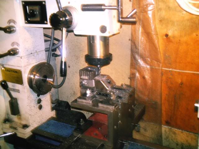
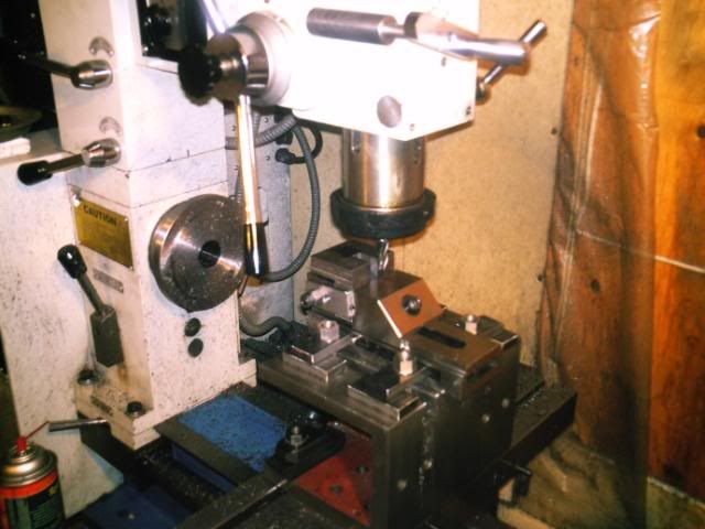
Pictures of the milling operations weren't great, as I was spending all of my time thinking and cranking.  Most of the cutting was done at very shallow depth and slow feed due to my machine & setup's complete lack of rigidity.


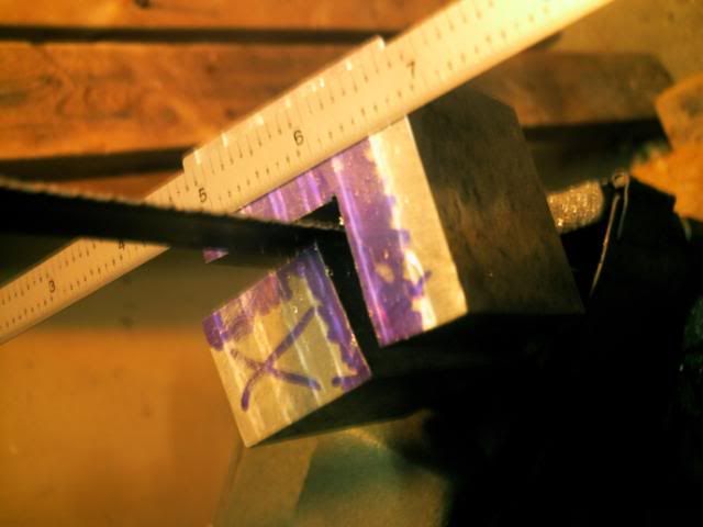
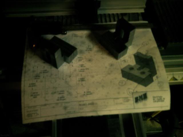
Back to the bandsaw to reveal more of the part within!


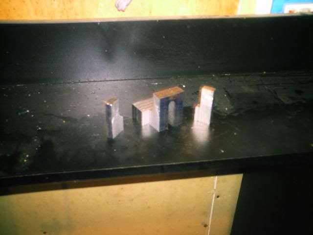
Alas it's starting to look like the CAD model!


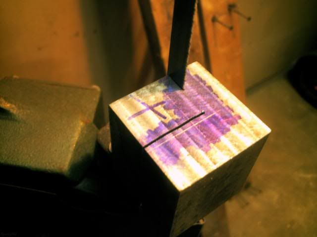
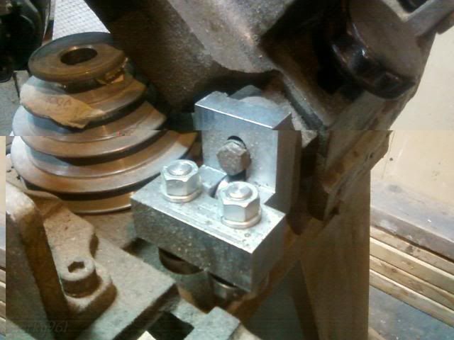
Once again on the mill to cut the groove in the back.  The slot for the bolt and guide bearing was cut using two setups.


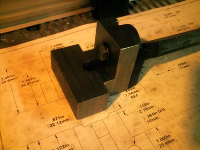
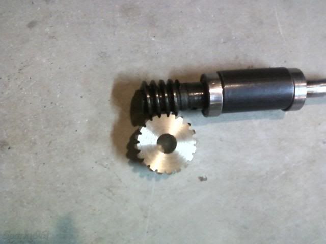
Skipped a few steps and pictures, but here it is mounted on the saw with bearings and all:


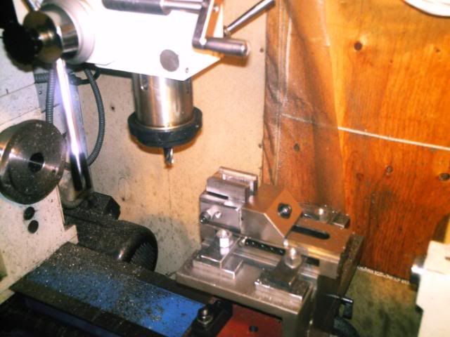
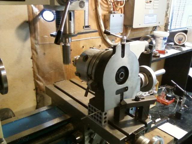
This setup should be looking familiar by now.  It's how I use my rotary table most of the time.  But there's a bit of a twist this time.  I have the rotary table angled down by 5 degrees to account for the lead of the worm gear.  I would probably try something a bit more stable next time, but this didn't move despite the single-point hammering away.

It's hard to get it up high enough so that the spindle reaches far enough to cut while keeping everything nice and rigid.  Nature of the beast, I suppose... and I grudgingly live with it until I have space/money/time for a better setup.


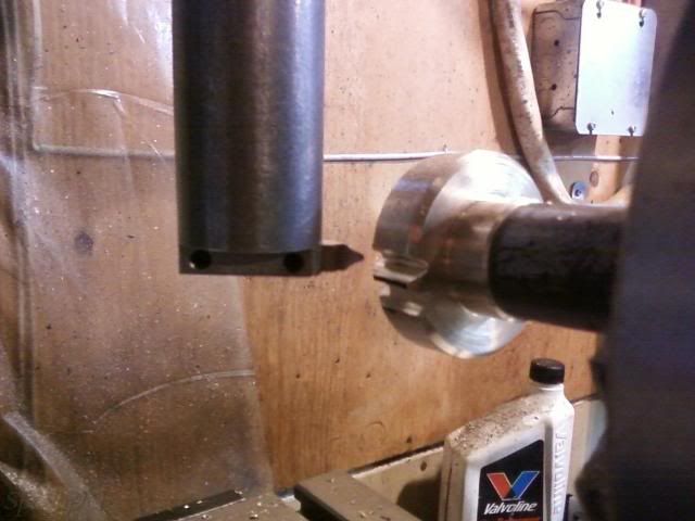
To help out a bit, I made up a very rigid single point gear cutting tool.  It's like a fly cutter but the tool is perpendicular to the spindle - not sure what the name would be.

I hand ground the tool bit using the old gear as a checking gauge.  After a bit of stoning we're off to the the races.  Material was generously donated by a friend of a friend - some sort of very expensive looking bronze.  I had made up the blank and arbour a few months ago and didn't take photos - pretty standard stuff there. ;)  I was going to make one out of aluminum too and use it to verify the setup, but that just didn't happen.

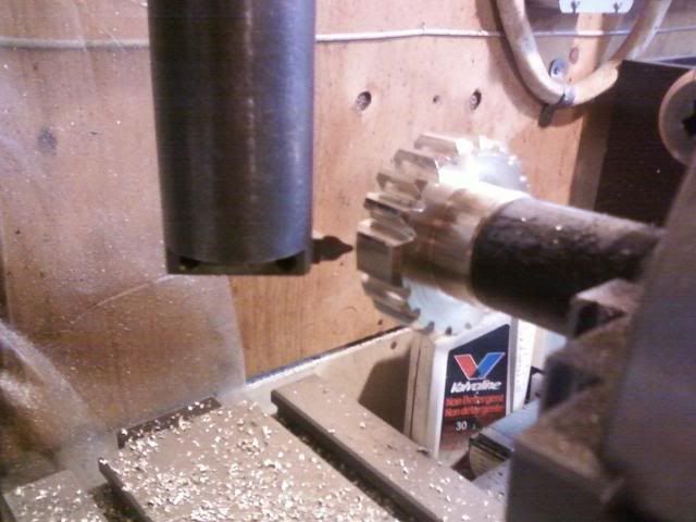
Dividing using the rotary table was simple because 20 teeth means all even numbers.  I should note too that the first time around I cut to the full depth I thought would be correct.  Slow and steady and it cut nicely albeit very noisily. 

Skipping ahead a few chapters, I ended up re-mounting this and cutting around the whole thing 2 more times before it fit.  Two things I did right, though not on purpose: Don't tear down the setup before checking the part, and when making a difficult one-off part cut small, check fit, cut a bit more, repeat.


Making the last cut - WOO HOO!  (hours passed between the two shots)


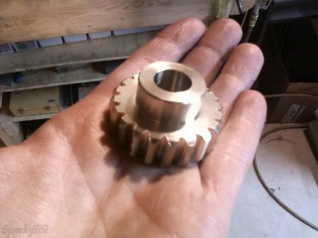
Mostly done, just needs hole cross-drilled for a roll pin and a keyway cut.


After checking the fit, I found the gears were way too tight.  I could turn them by hand with considerable force but after re-cutting them multiple times I was worried it would become too loose if I did another machining pass.  So, a bit of thinking and a bit of reckless caution thrown into the wind and I decided to run them in - using something like what may have been in there originally, OIL AND GRIT.  Now, generally you don't want to be throwing sand into the running gearbox of any machinery but let me tell you the process worked FANTASTICALLY!  I used a haphazard combination of chainsaw oil, 10W30, penetrating fluid, granite dust, and some of the aluminum oxide and silicon carbide dust swept up from around my grinder.


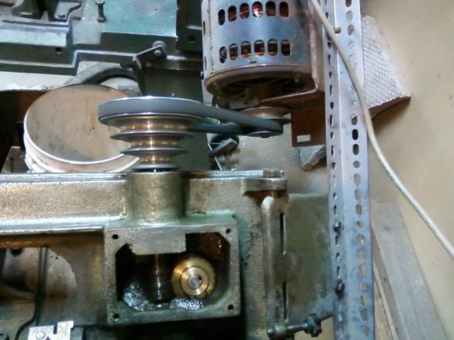
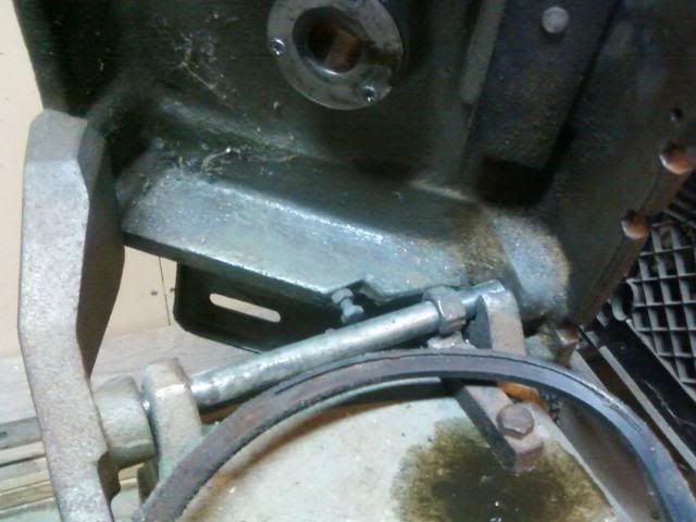
If you saw my thread on the repulsion motor (http://madmodder.net/index.php?topic=6574.msg70005#msg70005) the next picture might make more sense.  Really, I didn't know I had a motor that turned the right way.  I just needed to make it turn and it was getting very late!  The gears got a bit hot while it was doing it's thing, but they ran in to a nice fit with very little resistance.  At this stage the gear is just held on the shaft with a light friction fit.  It didn't slip while I did this, otherwise I would have had to put in the keyway and/or roll pin first.  Let's just say I was excited to see them turning together. :)


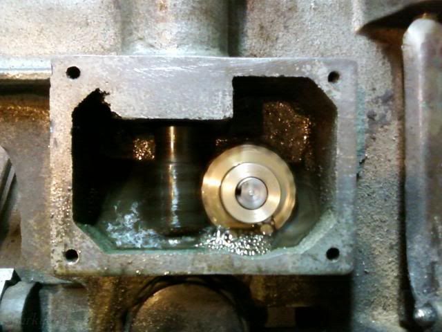
After all of that crazy fun, I did a thorough cleaning and covered the openings with duct tape to keep them clean.


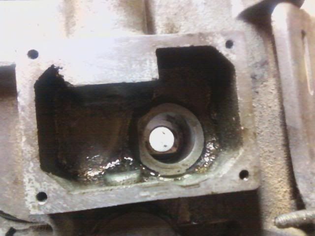
Still left to do is to finish the gear details and then I have some ideas for this mess... If you look carefully, you'll see that someone has broken off the right bearing and replaced it (farmer style) with a nut.


Well, that's all I have for now.  We'll see how many months before I update this thread again.  Thanks for your interest!

-Sparky

Offline -steves-

  • Full Member
  • ***
  • Posts: 138
  • Country: gb
Re: 4x6 Rebuild
« Reply #12 on: January 05, 2012, 02:51:30 AM »
Thats really cool  :thumbup:
very new to all this....

Offline krv3000

  • Hero Member
  • *****
  • Posts: 2183
  • Country: gb
Re: 4x6 Rebuild
« Reply #13 on: January 05, 2012, 03:21:57 AM »
HI nicely dun keep at it

Offline sparky961

  • Hero Member
  • *****
  • Posts: 844
  • Country: ca
Re: 4x6 Rebuild
« Reply #14 on: January 10, 2012, 11:28:54 PM »
Thanks for the encouragement gents.  It turns out this project has been doing a surprisingly good job of holding my interest!  Here are some more pictures and comments in the continuing saga...

My plan is to completely replace the pivot bearings, so the first step?  Out with the old...


First question, how the heck do I hold it?  The bandsaw base is almost the same size as the base of my machine!  Here's where the inspiration from Ade's huge block of aluminum comes into play.  I shall make it fit!!!


In the picture above, it hangs off the front quite a bit and causes the carriage to slide with increased effort.  I wouldn't want to use the machine like this all the time but I think this small abuse should be ok. 

After quite a few passes with the fly cutter, I'm rewarded with a shiny swath the entire length of the part.  In retrospect, after zip cutting the old ears off I should have ground the stumps down further to make the machining go quicker.  Oh well, lesson learned... cast iron machines quick enough anyway.

(edit) I should probably add a "do as I say, not as I do" here, and mention that might not be a good idea to use a drill chuck for fly cutting.  I know this, but sometimes I need to get more length on my tooling because I have no adjustable knee or column, just the spindle and it's minimal travel (/edit)


Oh, I do love the look of a fly cut surface!  Except for the remnants of the tapped hole in the back and a small casting defect that was revealed, the surface is shiny, smooth and consistent.


While it was still playing piggyback with my machine, I laid out a hole pattern for where the new ones will be going.  This took a bit of thought because I had to take the thickness of the casting sides and make sure there was enough room for bolt heads underneath.


I didn't take a picture of the setup, but after I was all done with the top side, I flipped the whole thing over and used a similar setup to bolt it down.  I carefully milled a round "land" for each bolt head - required because of the casting's sloped inner surfaces.


I didn't take pictures of making the new ears, but it was pretty straight forward.  I used 3/4" x 2" HR bar, 1018 or 1045 I think, saw cut to length and then milled off the chamfers while holding at a 45 degree angle in a milling vice.  Two M8 x 1.25 holes were drilled & tapped in the bottom to correspond with the mounting holes drilled in the saw base.  The pivot hole was drilled shy of 5/8 then reamed to final size.  An oil-lite bushing was then pushed in using the bench vise and back to the mill once more for a quick 1/2" ream to size (required because the thin bushing closes in very easily on the inside, even with a light press fit).


I installed the bolts loosely and inserted the 1/2" shaft, then pushing both to the front of the mounting hole to get pretty good alignment with the holes, tightened them down.  I must have done something right because there was no play in the shaft yet with very light tapping it slides through the bushings without binding.


Since I'm going the distance with this rebuild, I'm thinking I'll design a new stand to replace the all-too-common flimsy sheet metal one.  I've seen a few other designs, but so far none of those has captured my interest.  I'll have to go through them again and see what I come up with.


-Sparky
« Last Edit: January 10, 2012, 11:53:02 PM by sparky961 »

Offline jcs0001

  • Sr. Member
  • ****
  • Posts: 286
  • Country: ca
Re: 4x6 Rebuild
« Reply #15 on: January 11, 2012, 02:15:35 PM »
Sparky:

Great job with limited tooling.  I'm sure lots of us experience that - insufficient tooling or too small to do what we want.  I look forward to your ideas for a stand - mine has the flimsy sheet metal stand and I haven't got around to doing anything about it.

John.

Offline awemawson

  • Global Moderator
  • Hero Member
  • *****
  • Posts: 8967
  • Country: gb
  • East Sussex, UK
Re: 4x6 Rebuild
« Reply #16 on: January 11, 2012, 03:36:41 PM »
To get the correct form for your wormwheel you should gash it as you have but not to full depth, then hob it with a facsimile of the worm that has axial gashes to form cutting edges. The wormwheel needs to end up shaped like a diabalo so that it partly envelopes the worm. A piece of silver steel turned to the shape of your worm, gashed and then hardened would be quite sufficient.

Andrew Mawson
East Sussex

Offline sparky961

  • Hero Member
  • *****
  • Posts: 844
  • Country: ca
Re: 4x6 Rebuild
« Reply #17 on: January 11, 2012, 03:52:10 PM »
To get the correct form for your wormwheel you should gash it as you have but not to full depth, then hob it with a facsimile of the worm that has axial gashes to form cutting edges. (snip)

Ya, I know I'm cheating a bit with the way I did it.  :)

I took more of a "make it work" approach and mostly copied what was already in there.  I'm not sure if the pictures show it clearly enough, but the mangled one from the factory was cut similar to the way I did it but with a smaller diameter cutter.  It looks like they entered the work from the side so that the space between teeth would be contoured a bit.

I knew that it wouldn't mesh perfectly, but considering the application I think quite a bit of slop would be more than acceptable.  Some day when I'm making something that needs the accuracy, I definitely want to try hobbing the worm wheel as you've described.

-Sparky

Offline Andrew_D

  • Jr. Member
  • **
  • Posts: 44
Re: 4x6 Rebuild
« Reply #18 on: January 14, 2012, 05:10:05 AM »
Since you are redesigning the stand anyways, this would be a good time to incorporate a coolant system...

Andrew

Offline ETC57

  • Newbie
  • *
  • Posts: 3
Re: 4x6 Rebuild
« Reply #19 on: February 15, 2012, 04:19:01 PM »
 Great build Sparky! :thumbup:

 Looking forward to your next update!! :clap: :clap: :clap:

 Jerry. :beer:

Offline sparky961

  • Hero Member
  • *****
  • Posts: 844
  • Country: ca
Re: 4x6 Rebuild
« Reply #20 on: February 15, 2012, 05:30:52 PM »
Jerry,

Thanks for the encouragement.  I've gotten busy with that annoying thing called "life", but definitely need to get back onto this. :)

-Sparky

Offline sparky961

  • Hero Member
  • *****
  • Posts: 844
  • Country: ca
Re: 4x6 Rebuild [COMPLETED]
« Reply #21 on: February 16, 2013, 03:53:40 PM »
Bumping a really old thread here, but for a good reason.  This will be my last post to this thread because the build is done and I've sold the saw.

Since ending off, I did a few more things to finish off the rebuild:
- Make and install an adjustable stop for the blade arm
- Install an auto shut-off switch and wiring
- Purchase (ya, cheated there too) pulleys and make adapter sleeves to fit shafts

Umm..... you know, I think that's all that I did since then :)  Like many of you can probably relate to, my interest in this project started to dwindle over time.  If I didn't already have a band saw that works well, I might have taken it a bit farther but I decided I needed the space and that it was time for someone else to enjoy the result of my efforts.  I am confident that the saw will perform better and last longer than the was it came from the factory.

Taking all of my time into consideration, I'm sure it was a financial loss but that wasn't the point.  I enjoyed making all of the parts and seeing it come together.  And, of course, every minute you spend working on things improves your skill and experience.

Here are the final pictures that I took last night when I posted the ad...


Closure.  What's next?

-Sparky

Offline PekkaNF

  • Hero Member
  • *****
  • Posts: 2523
  • Country: fi
Re: 4x6 Rebuild [COMPLETED]
« Reply #22 on: February 17, 2013, 10:05:33 AM »
.....
Closure.  What's next?

-Sparky

Retarder and suds.
http://madmodder.net/index.php/topic,7937.msg84951.html#msg84951

Retarder works, coolant works, but not very elegant yet. Flood if you use it often.

Pekka