Author Topic: Elmer's Kimble engine  (Read 51960 times)

Offline arnoldb

  • Hero Member
  • *****
  • Posts: 515
  • Country: na
  • Windhoek, Namibia
Elmer's Kimble engine
« on: December 11, 2011, 02:22:21 PM »
Elmer's Kimble engine has been on my to-do list for quite a while, and have literally been nagging at me to be built  :dremel:.

I can't seem to find any other build logs on it, and have only found one short Youtube video of one, so this is a bit of a journey into the unknown.  The engine seems relatively straight-forward to build, but thinking through the processes, there are a couple of potential gotcha's - most notably that everything thing must be kept very square to prevent binding.

I have found one measurement wrong on the plans so far as well.  The sizes for the mortise and tenon joint on the vane shaft does not match...  A 1/4" tenon will not go into a 3/16" mortise, so those sizes I'll adjust as needed.

As usual, I'll be using whatever material I have on hand during the build - and will deviate a little from the plans in areas where dimensions does not matter.

I started on the sub-base and base today.  The plans call for a 1/8" sub-base and 1/2" base, so I settled for two bits of 10mm hot rolled steel bar   :coffee: :

The thicknesses are not important - as long as they are thick enough together to accommodate the flywheel swing.

Both bits were sawed and then milled to size, and the flat faces roughly fly-cut to get rid of all the mill scale:


A bit of lay-out on the base:


Then I clamped it to the sub-base and started drilling 3mm clearance holes for all the mounting bolts:


I wasn't feeling in the mood to mill out the entire flywheel cut-out, so I chain-drilled the end, pushed some pins through the holes to keep things matched up and then used the band saw to cut down the sides leaving about 0.5mm of metal to remove with the mill:

I just kept a careful eye on the cut to make sure it didn't stray too far.  Because of the angle of the saw head, I had to stop early, and finish off the last short sections of the cuts with the saw in vertical mode.

Now, who says a shifting spanner has no place in the shop :dremel: - I used a small one to break out the unwanted sections from the cuts:


The cut-outs were cleaned up with a 4mm end mill; I just milled to split the mark-out line on the base:

My 4mm end mills are too short to do both the base and sub-base at the same time, so I used pins to align the base with the sub-base again and used a sharp scribe to mark the sub-base off the milled-out section from the base.  Then I just milled the sub-base to those lines as well.

Stopped here for today:


 :beer:, Arnold

Offline Stilldrillin

  • Global Moderator
  • Hero Member
  • *****
  • Posts: 4972
  • Country: gb
  • Staveley, Derbyshire. England.
Re: Elmer's Kimble engine
« Reply #1 on: December 11, 2011, 03:09:17 PM »
Hi Arnold.
Well..... I haven't much idea of what you're building, though I've found a 6 second video.......  :scratch:

So, I've clocked in, and settled down. Ready to watch another of your crackin' builds.  :D

You've made a fine start!  :clap: :clap:  :thumbup:

David D
David.

Still drilling holes... Sometimes, in the right place!

Still modifying bits of metal... Occasionally, making an improvement!

Offline rleete

  • Madmodder Committee
  • Hero Member
  • *****
  • Posts: 534
  • Country: us
Re: Elmer's Kimble engine
« Reply #2 on: December 11, 2011, 07:03:51 PM »
I started this several years ago.  Decided it was a little too much for my skills, and never got back to it.  I'd really like to see one running.
Creating scrap, one part at a time

Offline ncollar

  • Jr. Member
  • **
  • Posts: 10
Re: Elmer's Kimble engine
« Reply #3 on: December 11, 2011, 07:32:22 PM »
Arnold
I am going to be watching closely. This engine has had my interest since I bought the book. I have enjoyed it so far, now on to bigger and better things.  :beer:
Cheers
Nelson Collar

Offline DaveH

  • Hero Member
  • *****
  • Posts: 1413
  • Country: za
  • Kempton Park, South Africa
Re: Elmer's Kimble engine
« Reply #4 on: December 12, 2011, 04:57:14 AM »
Nice start Arnold, :thumbup:

Just got comfy and y' stopped  :D
 :beer:
DaveH
(Ex Leicester, Thurmaston, Ashby De La Zouch.)

Offline arnoldb

  • Hero Member
  • *****
  • Posts: 515
  • Country: na
  • Windhoek, Namibia
Re: Elmer's Kimble engine
« Reply #5 on: December 13, 2011, 02:05:42 PM »
Cheers David  :beer: - I think that must be the same video then (this one)...  One chap has drawn it up as a CAD model as well,but like I said, info on actual builds of this one's a bit scarce.  I found this video that shows the "cylinder" (vane) movement in the engine block, but the valving and passageways on Elmer's design is different; it uses a rotary valve.

 :beer: Thanks rleete; I also would like to see it running!

Nelson, thanks  :beer: - I envy you a bit now  :D.  I wish I had Elmer's book; I just have all the plans from downloads off the Internet.

 :lol: - Cheers Dave  :beer: - I decided to keep the posts shorter just for you  :poke: :lol:

I stole a couple of hours in the shop after work today, and started on the bearing columns.  The plans call for 1/4" thick columns, and while I have some 6mm aluminium plate, I decided to rather make them from steel as well.  The base will be painted, and keeping the material the same will save some headache when it comes to that.  The columns need to be fairly close in thickness, as they will have the flywheel between them, and cranks and linkages on the outsides.  I used some more of that 10mm hot-rolled bar (It's cr@p stuff to machine, but I have about 4 meters of it, so it must be put to use :lol:) :


The edges were milled square and to size, one face fly-cut to get rid of the mill scale, flipped in the vise, and then I hogged down the thickness to 6.4mm with a 16mm end mill:


A 0.05mm fly-cut, and the ugly hog-marks were gone and the bit of plate at 6.35mm ;D:


Split the bit of plate down the middle on the band saw:

And then milled the sawn edges down to size.

One block was laid out and the two were then carefully clamped together - ensuring all edges matched up - and the lot clamped in the mill vise and drilled 8mm:

The main axle will be 6mm, but as it will be steel and the bearing blocks are steel as well, I decided that I'll add pressed-in phosphor bronze bushes.

The last step for today was drilling the columns 2.5mm to tap M3 later for the mounting screws:


 :beer:, Arnold

Offline ncollar

  • Jr. Member
  • **
  • Posts: 10
Re: Elmer's Kimble engine
« Reply #6 on: December 14, 2011, 11:10:17 PM »
Arnold
Keep up the good work, looks great. I love it when a engine comes together.
Cheers :coffee:
Nelson Collar


Offline arnoldb

  • Hero Member
  • *****
  • Posts: 515
  • Country: na
  • Windhoek, Namibia
Re: Elmer's Kimble engine
« Reply #7 on: December 18, 2011, 09:30:12 AM »
Thanks Nelson  :beer:

Managed a couple of hours in the shop today   :D

I used the mill vise stop as a kind of parallel to get a good angle on the bearing blocks (the bottom corners of the blocks actually rests on top of the vise stop bar), milled off the angle, flipped the blocks over & repeated:


Then milled the tops close to round:


A quick bit of file-work smoothed off the milled facets:


Tapped the bases M3 for the mounting holes:


Turned up a couple of press-fit phosphor bronze bushes:


Then started on the flywheel.  I had a ring of phosphor bronze left over from the Coomber engine, so used that for the flywheel rim.  One side and the rim was already true, so I just used two 8mm toolbits to offset the rim to allow me to turn it down to thickness - of course, removing the toolbits before starting up the lathe!:


After a bit of turning and boring, I had the flywheel rim:


Then I turned a bit of 70mm diameter aluminium down for a light press fit for the rim (0.02mm over size)- I had to wait a bit for it to cool down before the final finish pass, as I didn't want it to shrink down too much after machining:


I just left the rim outside in the sun for a couple of minutes; it was a searing 38C here today and the sun was beating down mercilessly, so that heated the rim quite enough to allow me to lightly, but quickly tap it into place on the aluminium, and once it cooled it is staying very much put.  A careful clean-up on the rim and a face-off and I left things like that to go inside for a bit of time with the air conditioner. :


I did snap a photo of the base with the bearing blocks mounted; at least that's starting to come together now:

The parts just need a final clean-up to remove the last tool marks and a ding on the sub-base that I haven't noticed before, then some paint.

 :beer:, Arnold

Offline Doc

  • Jr. Member
  • **
  • Posts: 98
  • Country: us
  • Old but still usefull (I hope) ?
    • My Youtube Channel
Re: Elmer's Kimble engine
« Reply #8 on: December 18, 2011, 10:45:18 AM »
Nice looking base and that's going to be a sharp looking flywheel!

Offline sbwhart

  • Global Moderator
  • Hero Member
  • *****
  • Posts: 3530
  • Country: gb
  • Smile, Be Happy, Have Fun and Rock Until you Drop
Re: Elmer's Kimble engine
« Reply #9 on: December 18, 2011, 11:25:46 AM »
Going well Arnold  :thumbup:

Stew
A little bit of clearance never got in the road
 :wave:

Location:- Crewe Cheshire

Offline DaveH

  • Hero Member
  • *****
  • Posts: 1413
  • Country: za
  • Kempton Park, South Africa
Re: Elmer's Kimble engine
« Reply #10 on: December 19, 2011, 02:36:32 PM »
Arnold,

Nicely done :clap: :clap: :clap:

Nicely shown :clap: :clap: :clap:

 :beer:
DaveH
(Ex Leicester, Thurmaston, Ashby De La Zouch.)

Offline saw

  • Hero Member
  • *****
  • Posts: 1003
  • Country: se
  • lucky amateur
    • Svenssons AckordsWerkstad
Re: Elmer's Kimble engine
« Reply #11 on: December 19, 2011, 02:45:07 PM »
And another piece of art..  :clap: :clap: :clap:
_________________________
Greetings / Benni
http://myprojecty.wordpress.com/category/steam-engine/

Offline arnoldb

  • Hero Member
  • *****
  • Posts: 515
  • Country: na
  • Windhoek, Namibia
Re: Elmer's Kimble engine
« Reply #12 on: December 20, 2011, 12:03:17 PM »
George, Stew, Dave & Benni - thanks Gents  :beer:

Had a bit more shop time after work today   :dremel:

The flywheel-in-making was still sitting on the lathe as I left it Sunday, so I drilled and reamed it for the axle, trepanned the face to thin the web  and then flipped the whole lot around in the chuck, using bits of cardboard to prevent damage to the finished rim:


Then I faced off the excess aluminium, and trepanned this side as well:


Next up will be a bit of work on the rotary table, but I have to calculate a couple of angles and offsets first...

 :beer:, Arnold

Offline foozer

  • Full Member
  • ***
  • Posts: 194
  • Camano Island WA
Re: Elmer's Kimble engine
« Reply #13 on: December 20, 2011, 03:17:10 PM »
Now thats an interest, little bit held in a support gizmo held in the tool post. Take it the little bit is for the finer work and the support is to add some sense of rigidness. I like it, clever


Robert
Ignorance is Bliss, thus I aim for Perfection

Offline arnoldb

  • Hero Member
  • *****
  • Posts: 515
  • Country: na
  • Windhoek, Namibia
Re: Elmer's Kimble engine
« Reply #14 on: December 21, 2011, 12:54:20 PM »
Thanks Robert  :beer:
:lol: You're giving me way too much credit there for being "clever"...
Actually, I got a job lot of good quality 4mm x100mm long HSS round blanks a year or two ago for a VERY reasonable price, and that's my way of using them.  The "holder" is a useless-to-me carbide tipped internal threading tool that I drilled and threaded to mount them in.  I just cut the HSS blanks in two or three pieces, mount them in the holder and grind away to make up small toolbits as I need them - the holder makes it easy to grind them as well as use them  :dremel:
Much quicker and cheaper than grinding bits out of bigger pieces of HSS  :thumbup:
I don't even bother locking the height-adjuster screw on the QCTP holder I use it in; I just use it to screw the holder up or down to get the tip at the correct height and lock up & go.  But you are right, it is convenient to get into close corners with the small bits while maintaining a semblance of rigidity. In the photo there's a better view of the holder, a new HSS blank, a bit with one end ground up to make a very sharp shoulder on a turned bit in brass, and finally another bit with one side ground to part 2mm grooves in aluminium and the other end - though rotated out of view - is for single-point threading fine 60 degree threads.:

There are more bits, but all variations on the same theme; different widths of grooving bits for different metals, radius bits  and threading and V-bits.

No shop today; when I got home it was raining, so I popped a beer, fired up the Cracker loco and parked on the stoep playing trains & enjoying the cool damp breeze that's broken the last couple of day's 37C+ and humid heat  :D  Sometimes it's nice to just mellow out...

Did get a quick snap of a rather battered arachnid though - this one must have lost a fight somewhere...  This is a species of spider that I actively encourage to inhabit my house and shop, as they prey on all kinds of ants, insects, other spiders, does not spin webs and are completely harmless to household pets and other humans  :D:


 :beer:, Arnold

Offline foozer

  • Full Member
  • ***
  • Posts: 194
  • Camano Island WA
Re: Elmer's Kimble engine
« Reply #15 on: December 21, 2011, 01:20:10 PM »
Thanks Robert  :beer:
:lol: You're giving me way too much credit there for being "clever"...

couple of day's 37C+ and humid heat  :D  Sometimes it's nice to just mellow out...

Did get a quick snap of a rather battered arachnid though -

Arnold

Still looks the useful kit, gonna have to cobble up something similar, just snapped a 0.250 bit while boring a hole, too much unsupported.

Here its 37F - 2C or so, just warm enough to avoid the coat and cool enough to wish one was worn.

No spiders, they all sleeping. I give em names, the bride makes the funniest screech owl sounds when she shes one :)

Got me another bag of chips awaiting the next installment

Robert
Ignorance is Bliss, thus I aim for Perfection

Rob.Wilson

  • Guest
Re: Elmer's Kimble engine
« Reply #16 on: December 21, 2011, 03:20:24 PM »
Nicely done Arnold  :clap: :clap: :clap: :clap:


That spider could only be a few mill cross nothing for scale ,, :coffee:


Rob  :)

Offline DMIOM

  • Hero Member
  • *****
  • Posts: 676
  • Country: gb
  • Isle of Man
OT spiders
« Reply #17 on: December 22, 2011, 09:05:09 AM »
.....

Did get a quick snap of a rather battered arachnid though - this one must have lost a fight somewhere...  This is a species of spider that I actively encourage to inhabit my house and shop, as they prey on all kinds of ants, insects, other spiders, does not spin webs and are completely harmless to household pets and other humans  :D:


 :beer:, Arnold

shouldn't that be harmless ???? :beer:

(reminds me of the pseudo-science tale that did the rounds when we were kids (or maybe it was in Viz..)  Did you know that spiders have their ears in their knees? - here's how to prove it. Take one spider - make a noise and it will run away. Remove legs then make the same noise and it won't run away!    No spiders were hurt in recording this anecdote .....

Offline arnoldb

  • Hero Member
  • *****
  • Posts: 515
  • Country: na
  • Windhoek, Namibia
Re: Elmer's Kimble engine
« Reply #18 on: December 24, 2011, 06:15:30 PM »
 :beer: Robert, it works  :D.   :scratch: Snapped a 1/4" bit ? - that sounds like a tiny bit of over-enthusiasm was used  :palm: - best lighten up a bit on the cuts  :coffee:   :D.  At 2C without a coat you're getting on to Geordie territory - are you sure you're from the States ?  :poke:  :D --  :thumbup: Just poking a bit of fun at you; I know you're making chips other than the kind one eats  :beer:.  PS I'm glad I'm not close enough to hear the "owl"  :D

 :lol: Rob, cheers mate  :beer: - I'll have to get the wee 'un to climb on a scale the next time I see it...  might measure 0.5 gram across the top and bottom legs :coffee:  :D :D

DMIOM (I wish I had a more conventional first name to address you with  :)) At least it's not packing any "heat", so it's in effect un-armed completely...  I refrained from offering it a sip from my drink; that would turn it completely legless though...  :D

After a very merry week  :beer:, it was nice to get to the shop today.

I first did a C-o-C, then decided on an end mill size and then added a's, b's, thetas and so on, then used sines, cosines and other stuff to make some calculations:

 :Doh: Yes, yes, I know... Boring math stuff; I'm a sucker for punishment   :whip: - but then again, it's really not that hard to do, and very useful   :ddb: :ddb:

On to machining then.  I screwed the chuck to the rotary table and centered it on the mill with a 6mm bar chucked up - close enough for machining flywheel webs:

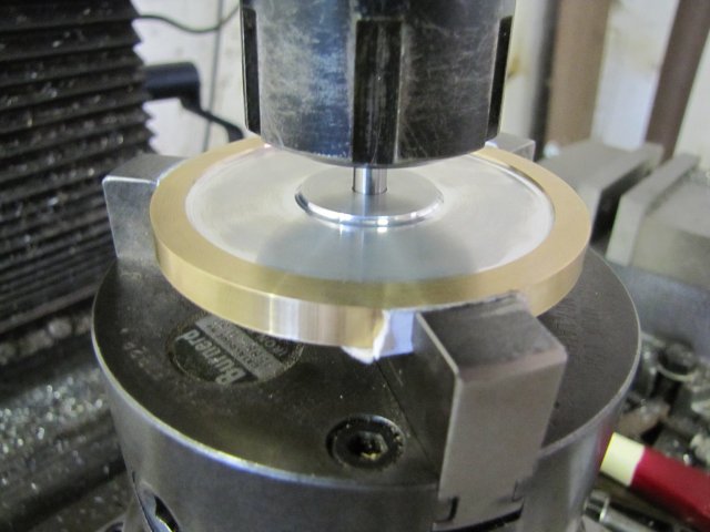
The X and Y hand wheels were zeroed here, and I just kept notes on the "boring maths page" (BMP from now on!) to remember which way I was cranking to compensate for backlash.

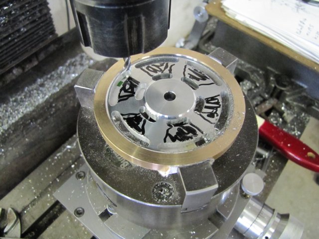
Then I drilled a bunch of 3.5mm holes according to the BMP:

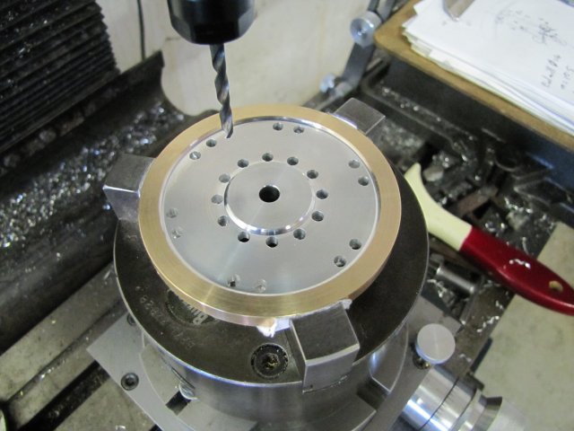
I want to finish off the webs with a 4mm  end mill, so I used the 3.5mm drill as it leaves a bit of lee-way for error, and can just be drilled without using a center drill (or even better a spotting drill) for each location.  If the 3.5mm drill wanders a tiny bit, that's OK.

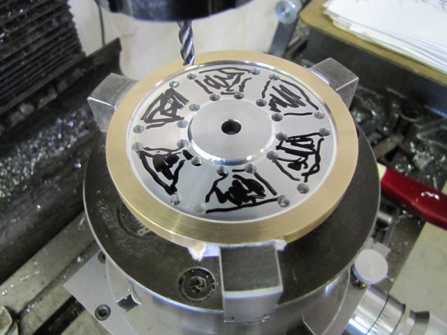
Next I marked out the sections that must be milled out - just to help prevent a brain-fart later:


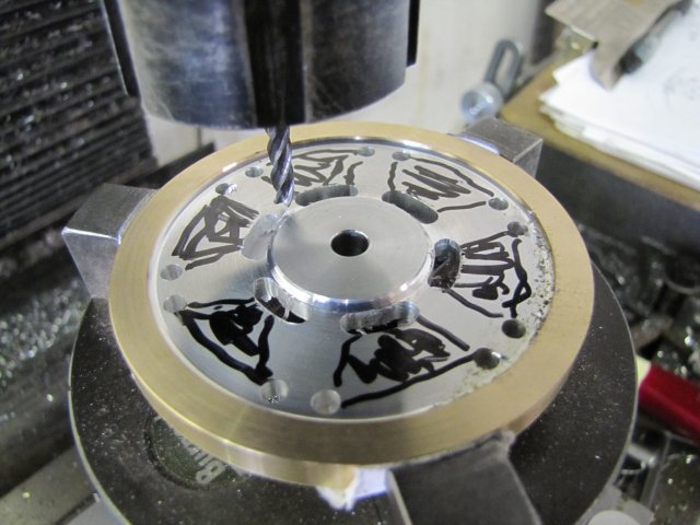
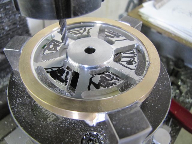
And a-milling-we-went.  First the insides radial edges closest to the hub, with Y offset for the radius and feeding the rotary table between angles - taking the readings off the BMP; 1mm deep Z for each pass requiring 4 passes per slot; no use to hog things out, as that could just end in heartache or lots of "bad" words from a variety of different languages - or both:


The outside radial edges followed using the same method:


Up to now, everything was done from the mill table's X zero point with only Y feeds for offsets.  For the next step, I once again referred to the BMP, offset the mill table in X and Y accordingly, dialed in the needed angle on the rotary table, and started on the straight sections of the webs - with feed on Y only:


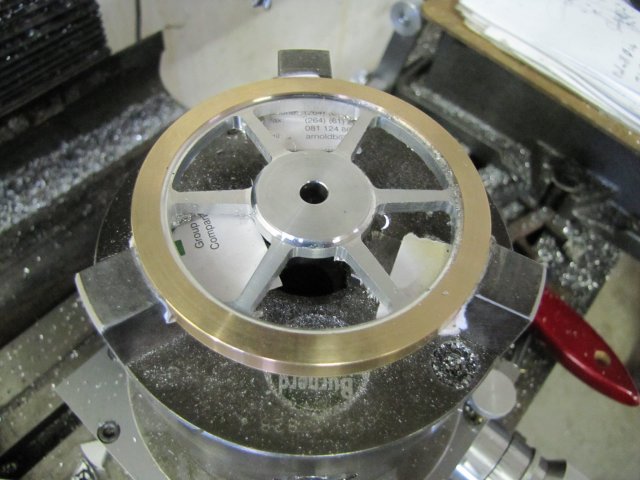
More reference to the BMP, other offsets on the mill table, and the last cuts were done:


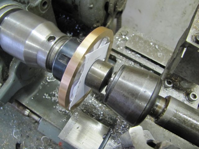
One side of the flywheel rim was still sharp from previous machining, so I mounted a bit of 6mm silver steel in the collet chuck on the lathe, pushed a bit of cardboard over it to protect and drive the flywheel hub, and then used a cone center with another bit of cardboard on the revolving tailstock center to mount the flywheel:


A quick lick with a file cleared off the burr on the rim, and then I just did some light file-work to get rid of burrs on the flywheel web.  A final rub with some emery paper rolled into a cylinder removed some more toolmarks, and I ended up with this:

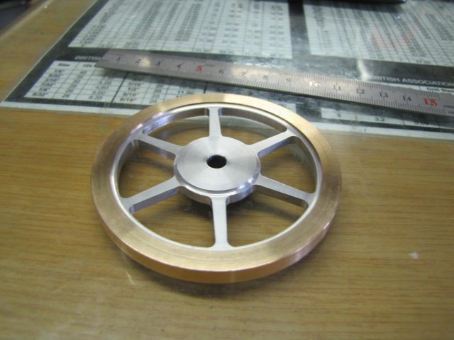
An OK-sort-of-looking flywheel.  I wanted lightly tapered spokes, but not too lightly tapered either.  Unfortunately, this is toward the "too lightly" side, so a lesson I can take forward.  4 degrees taper is too little on relatively short spokes like these  :(.  I'm not about to use some form of put-on-tool to correct this; in fact the only put-on-tool I have that is suitable for this application is called "re-make"   :coffee:

The BMP did get some additional scribblings on it through the process...  Yes, I KNOW... It's still a "Boring Maths Page", but it did help  :med::

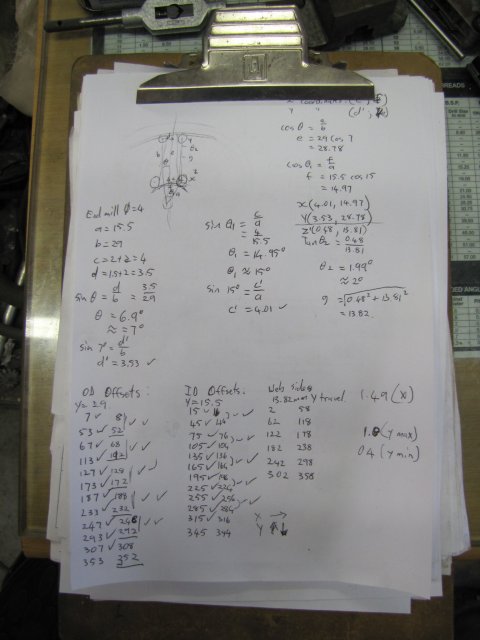
In fact, if I had to be more mathematically precise, there would have been a lot more calculations involved - but this was good enough for the job on hand.

The flywheel does fit on the base though, and looks OK.  I was thinking about painting the webs, but I have a hunch that will not be done; I'll decide about that once the base is painted:


Merry Christmas Everyone!

Kind regards, Arnold

Offline saw

  • Hero Member
  • *****
  • Posts: 1003
  • Country: se
  • lucky amateur
    • Svenssons AckordsWerkstad
Re: Elmer's Kimble engine
« Reply #19 on: December 25, 2011, 05:17:57 AM »
Beautifully work of art Arnold  :thumbup: :thumbup:
_________________________
Greetings / Benni
http://myprojecty.wordpress.com/category/steam-engine/

Rob.Wilson

  • Guest
Re: Elmer's Kimble engine
« Reply #20 on: December 25, 2011, 06:10:53 AM »
Very nice Mate  :clap: :clap: :clap: :clap: :clap: :clap: :thumbup:

Rob

Offline DaveH

  • Hero Member
  • *****
  • Posts: 1413
  • Country: za
  • Kempton Park, South Africa
Re: Elmer's Kimble engine
« Reply #21 on: December 26, 2011, 07:16:27 AM »
Arnold,

That is a very nicely made fly wheel.  :clap:  :clap:  :clap:

Great post as usual. :thumbup: :thumbup: :thumbup:

  :beer:
DaveH


(Ex Leicester, Thurmaston, Ashby De La Zouch.)

Offline arnoldb

  • Hero Member
  • *****
  • Posts: 515
  • Country: na
  • Windhoek, Namibia
Re: Elmer's Kimble engine
« Reply #22 on: December 26, 2011, 01:13:30 PM »
Thank you Benni :beer:

Rob, Cheers Mate  :beer:   :poke: Did you get that kiddie-car fixed so you can get on with the 626 now ?  :whip:  :lol:

 :beer: Thanks Dave !

Today's little bit...

From this point on, I'll work a bit slower, as this is the start to the more difficult parts of the build.

First, the engine block.  It must be 3/8" (9.53mm) thick.  I have some 10mm thick aluminium I could have used, but that bit is from extruded bar and very gummy to machine and tap, so I rather dug a bit of harder 12mm aluminium out of the stock bin:


That was then milled square and to size on all edges.  As I felt in the mood for some lathe work, I set it up in the 4-jaw on the lathe - just centered by eye and using a bearing shell as a parallel to the chuck body.  Some strips of aluminium drinks can were used to prevent chuck marks, and I used wire to bind down the parallel so that it wouldn't rattle around and damage the chuck face if it did happen to come loose:


Faced one side smooth, flipped the block around in the chuck, and faced the other side down to thickness:

There's a slightly rough bit close to the center, but it does not matter, as that's in an area that will be machined away later.
The block needs to be very parallel, and a check with a micrometer gave me less than 0.005mm (that's 2/10ths of a thou) difference measured in a couple of different locations.  My old girl (ML7) may be 40 years old, but she can still do it   :ddb:

Some quick marking out for bits that needed to be milled away and the double marking across is 1mm thick where it must be cut with a slitting saw later:


Cut-outs milled away; just hogged it down close to size with the 16mm end mill and then a light final pass either side to clean it up:


I bought a 5mm edge finder quite a while ago, but it was a bit rough and sticky and didn't work well.  Last week one evening I gave it a thorough wash-out with methylated spirits to get rid of the sticky oil that was used on it, mixed some Brasso with thin oil and lubricated the running face with that concoction and gave it a bit of a run, before once again washing it out thoroughly and just giving it some light machine oil.  Used it today for the first time, and it works beautifully  :dremel:  :

At 800RPM it wiggles around a bit, then smooths out, and then suddenly kicks out positively.  On the mill dials this was exactly on the same reading each time; I'll test it's accuracy more thoroughly at another time.

I used the vise stop and the mill's dials to coordinate drill the mounting holes 1.6mm to tap M2 later:


Then I slit the top section off:


As I didn't change the vise stop or dial zero-rings when slitting, I just used the same settings and readings as earlier to drill 2mm clearance holes through the top:


Next I tapped the holes in the bottom section.  I don't have long enough 2mm screws, so out with some bits of threaded rod:


More marking out.  The engine block layout on the plan is quite busy, and it's easy to get some measurements wrong.  In addition, the tangent sections are a bit difficult to lay out, as Elmer didn't give easy measurements to get to them.  As you can probably see, I ended up with a bit of a discrepancy in the thickness of the tangent sections - a combination of trying to manipulate the protractor and forgetting to compensate for the scribe tip's thickness:

Fortunately, the error is not a biggie; I stopped quite a while ago scribing deep lines on the work, as that's too difficult to get rid of later.  Both the scribe and the height gauge tips need a bit of sharpening as well; that's why the lines appear so thick.  I'll be using the vise stop to mirror the work as I go, so I only need good layout on one side anyway.

I then started drilling the 1.6mm holes for mounting the "cylinder" covers; these needs to be tapped M2 later.  Simple process to get the mirroring; locate a hole on the marked-out side and drill, then flip the workpiece end-over end and drill the mirrored hole on the unmarked side.  Here it is ready to be flipped to drill the last hole:


After drilling that last hole I stopped for the day.  I'm torn between making both the covers from some 2mm brass plate I have, or making the one cover from perspex so that the vane can be seen in operation.  The only suitable perspex I have is 3mm thick, and I'll have to check whether this will fit.  In addition, the vane shaft uses the holes in the covers as part of its bearing, so if I make a perspex one, I'll have to think up a way to insert a bush in it, and that's not so easy, as the inside part must be very flat as it is part of the sealing surface...

Time to think a bit  :smart:...

 :beer:, Arnold

Offline DavidA

  • Hero Member
  • *****
  • Posts: 1219
  • Country: gb
Re: Elmer's Kimble engine
« Reply #23 on: December 26, 2011, 01:14:17 PM »
Lost my password some time back and have only  just got around to setting up a new one.
Now I see what I have been missing.

Hope all you folks had a good Christmas.

All the best

DavidA

And yes,  I have written the new one where I can find it. :wave:

Offline millwright

  • Sr. Member
  • ****
  • Posts: 273
  • Country: gb
  • Leeds West Yorshire
Re: Elmer's Kimble engine
« Reply #24 on: December 27, 2011, 05:26:30 PM »
 Hi Arnold
Been following the build from the drawings, looking very good so far. As for the vane cover i do have some polycarbonate sheets 6in X3in that are 0.8mm thick, it may be a bit thin for You but Your welcome to a few, accoring to the words and music it should run on 10 to 15psi.
with the position of the cover plate screws i dont know if the pressure would tend to lift a poly cover or not, but a frame could be cut from brass to  match the vane opening  at one side to go over a clear cover so the vane is visible.  the brass could aso act as a bearing for the spindles.
 If You can use some polycarbonate let me know.
John