Author Topic: Elmer's Kimble engine  (Read 51975 times)

Offline rleete

  • Madmodder Committee
  • Hero Member
  • *****
  • Posts: 534
  • Country: us
Re: Elmer's Kimble engine
« Reply #25 on: December 27, 2011, 09:39:23 PM »
Arnold, try a blank CD.  All stacks of CDs have a clear one at the bottom to protect the surface of the good ones from scuffing. 
Creating scrap, one part at a time

Offline arnoldb

  • Hero Member
  • *****
  • Posts: 515
  • Country: na
  • Windhoek, Namibia
Re: Elmer's Kimble engine
« Reply #26 on: December 28, 2011, 05:25:11 PM »
Cheers David  :beer: - Thanks; Christmas was nice and quiet  :thumbup:.  Passwords...  :doh:  :lol:

Thanks John  :beer: ; I really appreciate your offer.  I'll find some locally; will be cheaper and quicker than postage from the UK  :thumbup:.  I was thinking along the lines of a brass hold-down frame as well  :thumbup:.

Rleete, thank you  :beer:; Great idea; I checked with a CD blank but its a bit small.   I have a bag full of CD jewel cases that can be used though :thumbup:

I'm shooting for less than 5 psi running pressure (hopefully purely breath power) and I won't ever use this engine on live steam, so the cover could be thin.  But after another look at the plans, its easy to fit a thicker cover on the one side of the engine; the two shafts just needs to be made a bit longer. So I have an idea what I'll be doing; it will take a bit of extra work, but should be worth it.

 :D The weekend is getting closer  :dremel:

 :beer:, Arnold

Offline arnoldb

  • Hero Member
  • *****
  • Posts: 515
  • Country: na
  • Windhoek, Namibia
Re: Elmer's Kimble engine
« Reply #27 on: January 07, 2012, 08:58:56 AM »
Wow - what a hot start to the New Year; it's been consistently in the 38C plus range here for the last 2 weeks, so I didn't even bother to venture into the shop and rather spent some quality time indoors upgrading my computer and a lot of software on it.  This morning I grabbed an hour shop before the heat got to me again.

I started drilling the port holes in the engine top:


Half-way through the first hole, the mill started making a funny noise; a quick check and the draw-bar had started unscrewing:

I don't know if the heat could have had an effect on it; I don't over-tighten the draw-bar and it could be possible that the heat allowed it to stretch just enough to come loose...  That's something I'll have to remember to be on the lookout for.

All set up to cross-drill the long port holes.  I used a small square as both a parallel and a way to keep the block square vertically.  The wire is to feel when the hole breaks through into the other passages:


As I was peck-drilling these deep 1.6mm holes without any lubrication, I kept a careful look-out for the drill tip clogging up like this:

Whenever that happened, I stopped the machine and cleaned the tip thoroughly.  If one don't, that's a sure-fire way to break off a drill in a deep hole.

At that point, the shop got too hot again, and I moved inside.  Out of pure idleness I made a short video on using the wiggle-wire:


At least this afternoon some cloud cover came in, and there's the rumble of thunder in the distance.  A good rainstorm would help to break the heat spell, so hopefully it might be cooler tomorrow so I can actually get something done.

 :beer:, Arnold

Offline DaveH

  • Hero Member
  • *****
  • Posts: 1413
  • Country: za
  • Kempton Park, South Africa
Re: Elmer's Kimble engine
« Reply #28 on: January 10, 2012, 09:49:41 AM »
Nicely shown Arnold,

Comming along nicely,

38 deg C mmmm................ seems to have got a bit on the warm side.

 :beer:
DaveH
(Ex Leicester, Thurmaston, Ashby De La Zouch.)

Offline arnoldb

  • Hero Member
  • *****
  • Posts: 515
  • Country: na
  • Windhoek, Namibia
Re: Elmer's Kimble engine
« Reply #29 on: January 14, 2012, 01:00:27 PM »
 :beer: Cheers Dave.   :palm: It's been extremely hot here; the weather office actually called it a "heat wave", and that's very rare.  Seems to be doing Namibian Breweries good though; I drive past their plant every day, and usually they're a bit quiet after the New Year, but they seem to be going full blast!

 :ddb: It's been cooler here the last couple of days, and after a run-around to shops this morning I got some more done on the Kimble, though I fluttered around all over the show.  Must be residual heat-stroke or something...

Instead of checking exactly where I ended off last week, I jumped in with a bit of perspex hacked off a salvaged old line-printer "window":


The perspex is 4mm thick, but that's not a problem as the one side of the engine where I want to put the clear engine cover can accommodate it.  I'd decided to make an insert from 2mm thick brass plate to act as the bearing.

To protect the perspex, I just coated it with masking tape, leaving the section that I wanted to mill out for the insert open:


The mill was still set up to drill holes all over the engine's top, and fortunately I thought to check if I'd finished all the holes in the top last Saturday.  Good thing I checked; I'd forgotten to drill the exhaust ports; in fact, I'd never even laid them out on the top.  So that was done first.  Then I had to drill the holes.  There was no way to get in close enough to spot drill first, so I just had to take the plunge and drill with the 1.6mm drill and hope it wouldn't wander:

As I couldn't drill straight through for both ports in one go, I had to flip the workpiece and drill from the other side as well.  I don't know if I was purely lucky, or if I'd spent enough time to set up accurately, but both holes intersected perfectly.  Looking through it, it's impossible to see that it was drilled as two separate holes.

With all the holes (  :palm:) in the top completed, I started on the brass insert for the perspex cover, purely because I'm lazy and it's easier to make it first and then mill away the perspex cover and use the insert to check the fit.  Holding smallish bits of plate is always a bit of a problem, so I opted for the tooling plate to hold it down to mill to width:


The perspex cover followed to cut out the insert space:


While I was set up on the tooling plate, I also looked for a nice piece of flat 2mm brass plate for the other side-cover, and squared up two sides of that as well:


I nearly started tapping all the 2mm side-cover mounting holes on the block and top, but then remembered that it would be easier to spot all the holes in the side covers using the block and top.  Then I saw some more holes I'd forgotten in the top; the 1.6mm mounting holes   :palm: - So I drilled those first:

Three down & one to go; just a flip away...

And done:


Cleaned the burrs off all the holes, and then glued the insert to the perspex plate.  I wanted to use epoxy glue, but when I found the tubes, all the hardener had leaked out, so I used superglue.  I hope it bonds with perspex.  Stopped for the day with this bunch 'o bits; not much to show for quite a bit of work  :coffee::


 :beer:, Arnold

Offline arnoldb

  • Hero Member
  • *****
  • Posts: 515
  • Country: na
  • Windhoek, Namibia
Re: Elmer's Kimble engine
« Reply #30 on: January 15, 2012, 10:50:24 AM »
This afternoon I clamped the covers and block together.  The perspex cover is sandwiched between the brass cover and the block, and the masking tape on it helps a lot to keep things from moving:


Off to the drill press to drill the 1.6mm holes.  With a small drill like this, I'm comfortable, yet very careful, to keep the workpiece firmly pressed down on top of the vise jaws  with my left hand and operate the quill with my right.  Because of the different layers in the sandwich, I peck-drilled the holes to keep swarf in them to the minimum while drilling:


When needing to move the clamp to a different position without letting things come apart, I just clamp the lot in a spot where the old and new clamp position wouldn't interfere.  Sometimes I do that with another toolmaker's clamp or in this case I used my small milling vise:

Here I wanted to flip the clamp from the left to the right to be able to drill the holes on the side where the clamp was before changing.

Next off to the mill to get rid of excess stock on the covers:


Silly me...  I'd put the studs and nuts on the top on the wrong side.  That made milling excess stock off the top more difficult, as I'd originally planned to just remove the nut and stud on the alternative top parts to finish to size.  The nut was too big to rotate, so I had to go around its back:


Next I turned up 1.6mm pins from some 4.3mm aluminium rod I have.  The toolbit is set up to leave a very slight taper on the aluminium, and the entire thickness is turned down in one go.  I used the small ER11 collet chuck, as it has a 4.5mm collet that can easily clamp down to 4.3mm - thus saving strain on my 5mm ER 25 collet:


The four completed pins/plugs.  As you can probably see, I just used a side-cutter to clip them off at just over the approximate length needed.  The two longer pins are to plug the holes right at the top of the engine top; they need to be long enough that their inside ends will be machined flush with the valve bore later on:


Here I installed one of the side plugs - a tiny dab of loctite on it, and hammer it into the hole with a small ball-peen hammer.  I knocked it good and flat, so that the plug will properly fill the hole, and once the excess is filed off, the plug will be completely invisible:


The two top pins knocked in and then filed flush; as you can see, they "disappear":


Same with the pin on the side; just lightly cleaned up here:

There are still tool marks on the sides of the block; these will be removed later in the build.

At this point I called it a day, as a big thunderstorm with high winds broke.  I'd left a lot of doors and windows open in the house, so I had to go and attend to a bit of mop-duty  :D


 :beer:, Arnold

Offline saw

  • Hero Member
  • *****
  • Posts: 1003
  • Country: se
  • lucky amateur
    • Svenssons AckordsWerkstad
Re: Elmer's Kimble engine
« Reply #31 on: January 15, 2012, 11:00:11 AM »
Nice build Arnold, I am very excited to see how this engine will come out  :thumbup: :thumbup: :thumbup:
_________________________
Greetings / Benni
http://myprojecty.wordpress.com/category/steam-engine/

Offline DaveH

  • Hero Member
  • *****
  • Posts: 1413
  • Country: za
  • Kempton Park, South Africa
Re: Elmer's Kimble engine
« Reply #32 on: January 17, 2012, 03:48:03 PM »
Coming along nicely Arnold.

Heat wave last week - floods this week :lol: :lol: :lol:

These weather excuses - a bit feeble mate :lol: :lol: :lol:

Nicely posted as usual though :clap: :clap: :clap:
 :beer:
DaveH
(Ex Leicester, Thurmaston, Ashby De La Zouch.)

Offline arnoldb

  • Hero Member
  • *****
  • Posts: 515
  • Country: na
  • Windhoek, Namibia
Re: Elmer's Kimble engine
« Reply #33 on: January 21, 2012, 12:58:32 PM »
 :beer: Thanks Benni - it's going a bit slow though...

Cheers Dave  :beer:.    :lol: I can add some more excuses...  Corporate take-overs, incorporating new corporate logos on electronic stationery, updating mail server signatures and on and on, but those are boring; it's more fun to blame it on the weather  :lol:

 :coffee: A bit of a boring update today...

The cover plates were still sticking together after last weekend's work - this was a result of using some old gummy masking tape to protect the perspex cover, so I lightly clamped them together just to make sure they didn't come apart, then opened the holes to 2mm for clearance for M2 screws, and then countersunk all the holes - easy to do by getting one hole to the correct depth and setting the drill press depth stop:

I had a bit of chatter in the holes; after a careful check,I found that these holes are actually a bit small for the countersink I have and it can barely open them up, so I'll have to buy a smaller countersink at some point.

Next up, tapping the M2 holes in the engine block.  My M2 taps are too short to tap the holes right through, so I had to tap the holes from both sides.  I used my tapping guide to limit the depth to tap too to half of the engine block depth (Apologies for the out-of-focus photo  :palm:):


Then I set about tapping all the holes.  For aluminium I use methylated spirits (rubbing alcohol) as tapping fluid, so I poured some into a spray-can top to make life easier.  The meths easily washes off any chips stuck to the tap, so it's easy; tap the hole; swash the tap in the meths and it gets both cleaned off and "lubricated" for the next hole:

The dark bits in the meths are chips that were washed from the tap.

Next a quick check, and as I thought, the shortest M2 screws I have are too long for the thin cover:

They are OK for the perspex cover though.

I've had to shorten M2 screws in the past, and it's a bit of a pain in the rear   :palm:.  Usually it was just one or two screws at a time so I'd fiddle along, but I was in no mood to fiddle ten of them...  So I diverted and built a little tool  :dremel:.
I just chucked up some 8mm hex brass, drilled it 5mm diameter (for M6 threading) 15mm deep, and followed the 5mm drill with a 2mm one another 4mm deeper.  Then I tapped it M6, and parted the piece off 17mm long.  On to the mill, and with  a 2mm slot mill, I milled a slot to the center of the 2mm hole, and a perpendicular slot wide enough to allow a 2mm screw's head to pass through far enough from the end to leave the cone section left by the 5mm drill intact. 


To my horror I discovered I'm out of 6mm silver steel to make the rest of the tool  :bugeye:, so I used a cap screw with the head sawn off and the end section of the thread relieved to clear the last bits of thread in the brass bit:


I wouldn't recommend using the above tool under power on the lathe, as the screw will easily deflect into the slot while machining.  I just used it chucked up in the lathe (with motor off) to saw off the excess length of the screws with a junior hacksaw with a fine blade:


It is convenient to have the tool in the lathe, as it's easy to clean up the cut face with a small file, and also file a slight taper around the cut face by rotating the chuck by hand.  These screws are stainless steel, and just outside the size for my favourite electronics cutter, if they were within it's size I would just have clipped off the ends with it and cleaned off with the file.
Ideally, I should have "relieved" the seat for the screw in the brass bit to 90 degrees rather than using the 118 degree cone left by the drill bit - but that would have meant making up a d-bit reamer and I wasn't in the mood for faffing around with that today  :coffee:.

The little tool works quite well.  Slip a screw in, tighten up the brass section on the arbor, saw off the little screw, file the nose flat to remove the burr from sawing, file a slight taper around the end of the treads then loosen the brass nut with a hand under it to catch the screw as it falls out...  It took me less than a minute per screw to get this lot shortened:


All the little screws in place - I need to make all the countersink holes about 0.1mm deeper though   :palm::


And the perspex cover screwed on:

To compensate for the thickness of the masking tape that was on there, I countersunk the holes slightly deeper.  Unfortunately, I over-compensated  :loco: - these are slightly too deep.

Hopefully, I'll have more interesting progress to report tomorrow.

 :beer:, Arnold

Offline saw

  • Hero Member
  • *****
  • Posts: 1003
  • Country: se
  • lucky amateur
    • Svenssons AckordsWerkstad
Re: Elmer's Kimble engine
« Reply #34 on: January 21, 2012, 02:57:05 PM »
Nice done Arnold I like your thinking and your way to make some easy tools. I will copy your idea when I need it. Your buildings skill is something too take after.  :clap: :clap: :clap:
_________________________
Greetings / Benni
http://myprojecty.wordpress.com/category/steam-engine/

Rob.Wilson

  • Guest
Re: Elmer's Kimble engine
« Reply #35 on: January 21, 2012, 03:47:02 PM »
Hi Mate ,,,,,,,,,,,,,,,, i see you have poked a few more holes in the build  :coffee:


Thunder storms  , too hot   :palm: ,,,,,,,,,, what ever next ,,, elephants in the yard , sandstorm maybe  :lol: :lol: :lol: :lol: :lol:

Looking good Arnold  :thumbup:


Rob

Offline Stilldrillin

  • Global Moderator
  • Hero Member
  • *****
  • Posts: 4972
  • Country: gb
  • Staveley, Derbyshire. England.
Re: Elmer's Kimble engine
« Reply #36 on: January 21, 2012, 04:58:47 PM »
Love your screw shortening system, Arnold!  :clap: :clap:

The rest of the work's great too......  :thumbup:

Keep on keeping on.  :D

David D
David.

Still drilling holes... Sometimes, in the right place!

Still modifying bits of metal... Occasionally, making an improvement!

Offline sbwhart

  • Global Moderator
  • Hero Member
  • *****
  • Posts: 3530
  • Country: gb
  • Smile, Be Happy, Have Fun and Rock Until you Drop
Re: Elmer's Kimble engine
« Reply #37 on: January 22, 2012, 01:46:57 AM »
Comming along great Arnold.

Like the screw shortening thing, I've a zillion M2 studs to shorten I could do with something like that.

Stew
A little bit of clearance never got in the road
 :wave:

Location:- Crewe Cheshire

Offline DaveH

  • Hero Member
  • *****
  • Posts: 1413
  • Country: za
  • Kempton Park, South Africa
Re: Elmer's Kimble engine
« Reply #38 on: January 22, 2012, 05:44:12 PM »
Great stuff Arnold  :thumbup: :clap:

Nicely shown as usual  :clap: :thumbup:

 :beer:
DaveH
(Ex Leicester, Thurmaston, Ashby De La Zouch.)

Offline arnoldb

  • Hero Member
  • *****
  • Posts: 515
  • Country: na
  • Windhoek, Namibia
Re: Elmer's Kimble engine
« Reply #39 on: January 24, 2012, 10:09:01 AM »
Many thanks Gents  :beer:

For those of you that found the little tool interesting, I went about it slightly wrong.  I knew I'd seen something like it somewhere but couldn't recall it's name.  John Bogs gave me a heads-up with a picture here on HMEM; it's called a Lantern Chuck.

Rob,  :lol: :lol: mate - a storm it was and it started with s..., and it wasn't sand...  :palm:  I'd better watch the amount of chilly I add to curry  :lol:

 :beer:, Arnold

Offline fixit

  • Jr. Member
  • **
  • Posts: 43
  • my first engine
Re: Elmer's Kimble engine
« Reply #40 on: January 27, 2012, 03:21:20 PM »
Good stuff !!!  thanks  i'm still looking over your shoulder for tips  and i like the wiggle wire

thanks Steve
northolt,near Mc donalds, next to Pc World

Offline arnoldb

  • Hero Member
  • *****
  • Posts: 515
  • Country: na
  • Windhoek, Namibia
Re: Elmer's Kimble engine
« Reply #41 on: January 28, 2012, 12:31:38 PM »
 Thanks Steve  :beer: - I can't exactly recall where I first saw the wiggle wire in use; I _think_ it was in one of Stew's (sbwhart) posts.  Nothing I do is new in machining; I'm just following tips I've picked up all over, so it gets really difficult to give credit where it's actually due.

Finally, a bit more done.  I'm taking things a bit slow on the engine block, as I don't want to make a mistake.

Last weekend I ended off with the countersink screws on the brass cover side still sticking out a bit.  For some of the machining operations to follow, I needed them flush - or just a tiny bit below the surface, but I also didn't want them countersunk too deep, as I think that looks plain ugly.

So after a careful measurement, I determined that they are sticking out just about the thickness of a business card.  So I used the plate just lying on top of the drill press vise jaws to set the drill press depth stop with the countersink bit engaged in one of the holes, then shoved a business card below the plate and touched up each hole:


Screwed up, all the screws are far enough below the surface; I could even rub the block over some emery to clean up the face a bit:

It would look even better if all the screws were "timed" so that their slots lie the same way... That's a project for one day when I try and do an "advanced" build   :lol:

On to one of the most important holes for the project; the main pivot hole.  This has to be very square to the engine body, otherwise the engine will be near-certain to bind as the vane will twist around in the block...  When I built my tooling plate, I marked it so that it go back in the mill vise in the same orientation that I faced its top, So I used that - did a quick check with a DTI to make sure that it was still level and square, and clamped the engine block to it, leaving it over-hanging just enough to clear a 6mm reamer passing through:


Then I drilled the hole through with a 3mm drill.  This was followed by a 5mm end mill.  The reason for the end mill is that it will true up the hole in case the 3mm drill had wandered a bit.  This was then followed by a 5.9mm drill; my theory being that it would follow the hole left by the 5mm end mill and not wander off course.  Finally I ran the 6mm reamer through the hole to get it to size and smooth:


Next the perspex cover was removed, and I set up the piece in the mill vise so that I could drill and ream for the rotary valve.  It was left raised enough out of the vise so that the cover plate could be removed without disturbing the set-up - then I drilled 2.9mm and reamed 3mm through the lot for the valve shaft:


The cover was removed, and I drilled the 3mm hole out to 9.8mm:


Next it was reamed to 10mm.  The plans call for a 3/8" hole for the valve, and I could have done that by boring the hole, but I had a careful look at the valve plans, and its easy to adapt it to 10mm:

The plans call for the "plugs" in the holes that were inserted from the top of the head to go in deep enough into the valve hole to be machined flush when reaming/boring the valve hole...   :ddb: I must have done something right, as they did "disappear".

I left off there for today.  Another important bit of machining is next, and I'd like to do that in one full shop session.
Back of block:


Front:


Overall progress...  I never coated the base with some oil, and it picked up a bit of surface rust from the damp weather we've been having.  Fortunately, nothing major, as it still needs some surface finishing and paint:


 :beer:, Arnold

Offline AussieJimG

  • In Memoriam
  • Sr. Member
  • *****
  • Posts: 381
  • Country: au
Re: Elmer's Kimble engine
« Reply #42 on: January 28, 2012, 02:46:09 PM »
Thank you Arnold, you keep teaching me new things. I like your tooling plate and the clamps - I can see how useful that is, and how simple to make. I feel a project coming on.  :ddb:

Regarding the screw heads lining up, that always creates lots of controversy. My grandfather always insisted that it was a sign of good workmanship. But he was a carpenter. Others insist that screws, like nuts, should be tightened to the correct torque regardless of the orientation of the slot. I have wimped out of the argument by using hex drive or square drive countersunk screws.

And the card trick is clever. I am enjoying this thread, thank you. :clap:

Jim

Offline doubleboost

  • Madmodder Committee
  • Hero Member
  • *****
  • Posts: 1619
  • Country: gb
  • Newcastle Upon Tyne
Re: Elmer's Kimble engine
« Reply #43 on: January 28, 2012, 05:54:16 PM »
Hi
Arnold
Just read your build  log
Very nice looking engine
That fly wheel turned out great :thumbup:
John

Offline arnoldb

  • Hero Member
  • *****
  • Posts: 515
  • Country: na
  • Windhoek, Namibia
Re: Elmer's Kimble engine
« Reply #44 on: January 29, 2012, 01:32:15 PM »
Thanks Jim  :beer: - I find that tooling plate invaluable now; in fact, at some point I want to make up some more of them and a lot more clamping kit.  If you're interested, here's a link to how I built it, as well as good advice from other home engineers.

John, Thank you  :beer:

 :D Today was one of those golden days in the shop that makes me love model engineering so much.  Just the right amounts of challenges, head-scratching, problem solving, lots of chips, and that whole kaboodle coming together in a nice end result.  Not really much to show as the end result, but the journey was the fun part.

For the next step in the machining process, I needed a sacrificial plate.  A bit of flat wood would have done as well, but I wanted slightly more accuracy than the wood would have given.  A while ago, the storage term for a whole lot of these ran out at work:

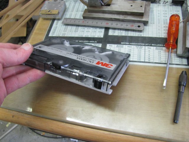
Anybody remember those?  As I'm responsible for IT Security at work, I signed them off for responsible destruction - told the bosses what would happen to them, and brought them home.  Taken apart, it's easy to snip the tape into thousands of pieces, and I get nice bits of tempered aluminium plate and a lot of precision pins out of them to use in projects.  Bosses are happy, and so am I.

I was spoilt for choice on how to do the next part...  Work on the lathe face plate, or boring head on the mill...  As there was quite a bit of milling to come, I decided on the face plate, as it's fun to change between machines for different jobs.
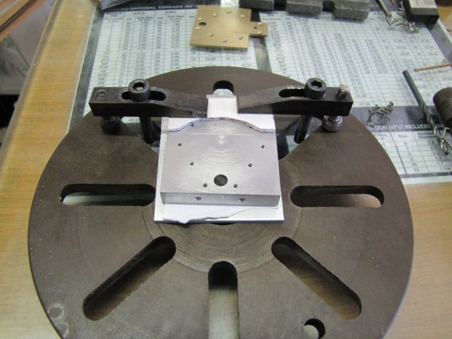
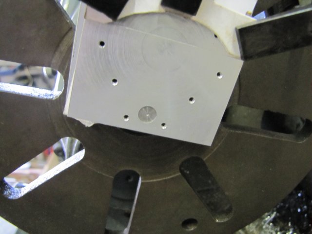
With a suitable bit of plate sawn from the old tape, I started setting up things on the face plate.  I find it easier to start setup on a table, and then mount the face plate to the lathe later:


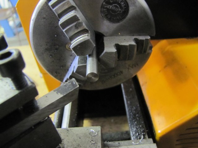
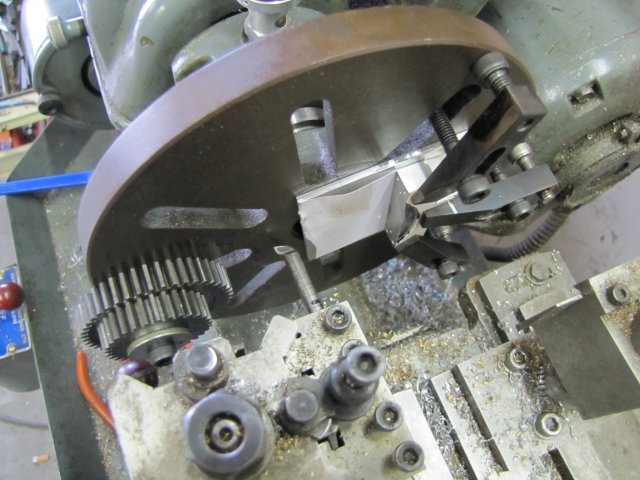
For the next step, the lot had to be mounted on the lathe, with the workpiece centered on the reamed hole.  Normally that would be done by sticking a pin in the hole and using a dial indicator or DTI to clock it up, but I know a pin chucked up in my lathe's tailstock is spot-on, so that's the method I used.  Face plate mounted on the lathe and the pin in the chuck:

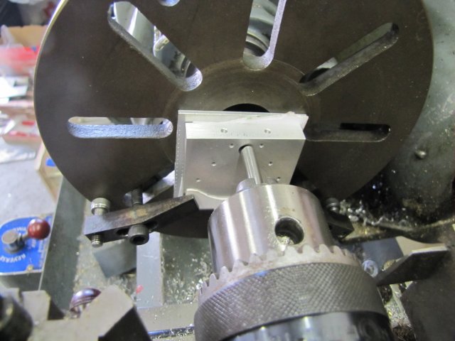
Not a bad job of eyeballing on the table before-hand  :)

With the workpiece loosened slightly, it was easy to lightly tap it into position to fit the pin:


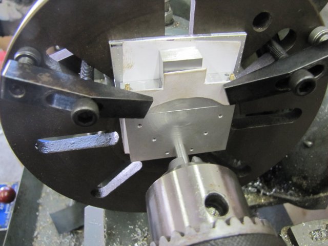
Then I added one more clamp - just to be safe, and to allow me to remove either of the side clamps so that I could get at the screws holding the engine body to the top:


 :Doh: I'd forgotten to lay out the cut dimension for the top...  Not so easy with a hole where the center should be either...  The small lathe is not mounted properly yet, but this is a very light job, so I fired it up and faced and lightly center drilled a bit of 6mm rod:


That was then sawn off and inserted in the hole in the block:


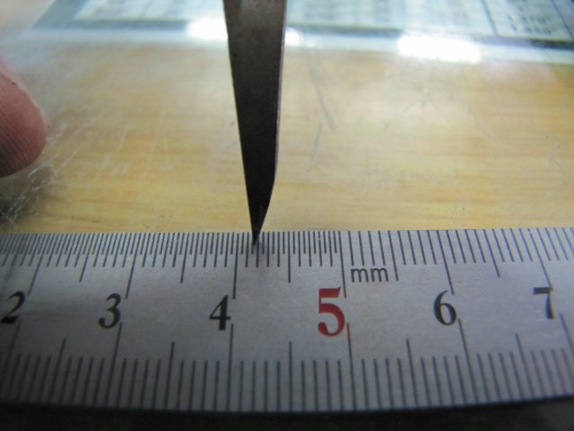
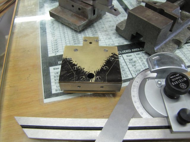
Next, I set my compass to 31.75mm.  Well, the photo shows that it was slightly less than that, but the camera's macro mode is much better than my eyeballs.  The reason the reading on the rule is 41.75mm is that the other end of the compass is sitting in the 10mm groove of the rule:


Target cut-line scribed:


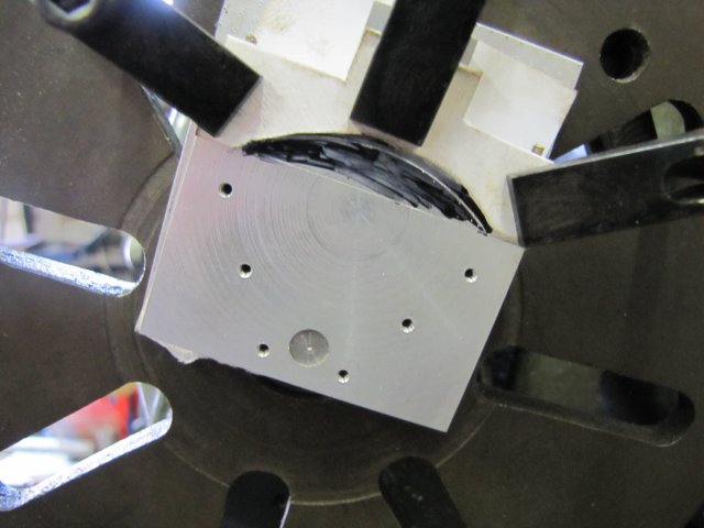
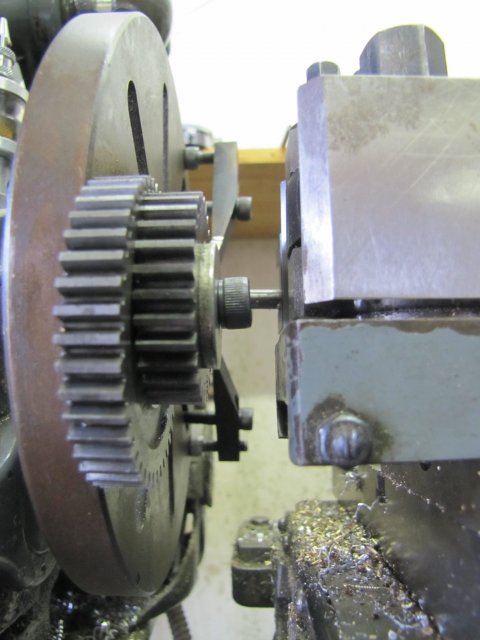
Then I added some counterweights to the face plate; No fancy math was used; just the fact that I have a fairly good feeling for how heavy the bunch of clamps and retaining nuts are - the gears were selected to approximate that.  And a final check from the top as to whether there would be any clearance issues:


And a view from the side - with the cutting bit set as deep as it would go:


Then I started putting some cuts on...  The cutting bit was honed super-sharp, but on the second cut I heard the dreaded sound...  A high-pitched squeal each time the cutter cut...  Chatter...  Stopped, and yes there it was (you can click on the image for a larger picture):


The finish in this cut must be smooth as silk; there would be no easy way to lap it accurately once done...  So I tried a stiffer toolbit; same thing - slightly finer chatter, but still there.
As the chatter was very fine, it would not take much to damp; I tried pressing on the back of the toolbit during the cut with a toothbrush handle, and the chatter went away   :ddb::


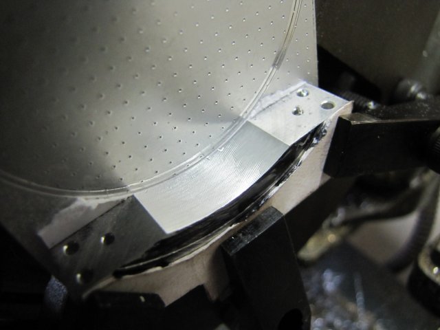
After the final cut with the toothbrush in position (once again, clickable for a larger photo):

 :ddb: :ddb: That's the finish I was after   :ddb: :ddb:

Some more lay-out followed:


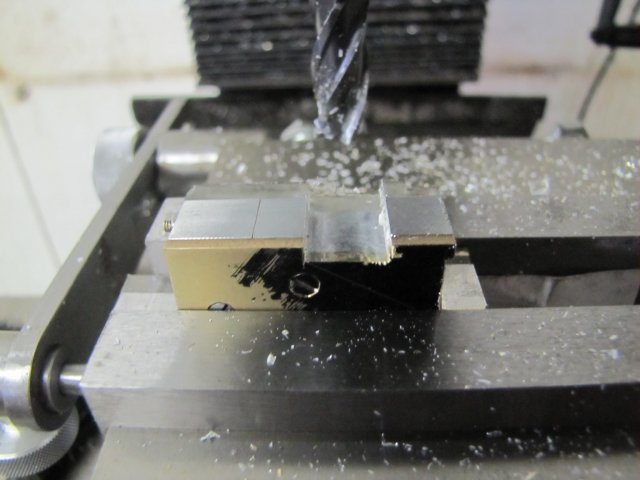
Then a quick bit of hogging in the mill:


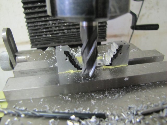
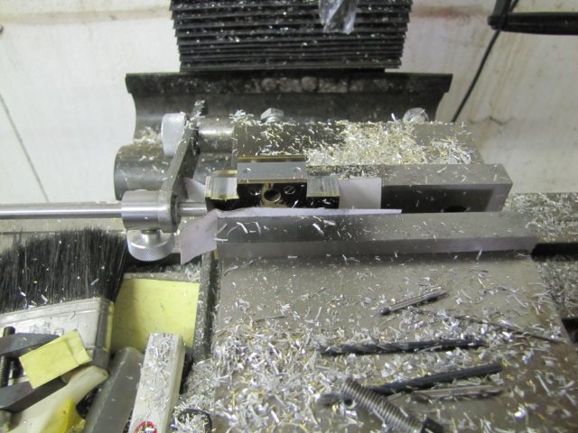
I just used some threaded rod screwed into the mounting holes to set the piece to mill out the angled sections:


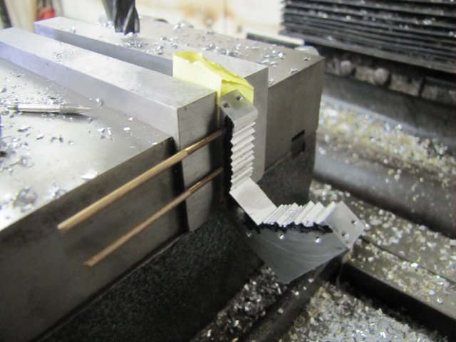
A little while later:


Then with both covers mounted on, a bit more lay-out:


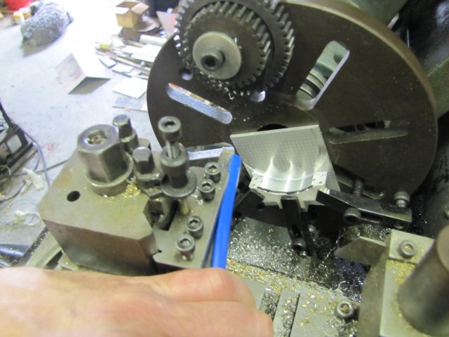
More milling - a bit more careful this time so as not to break out chunks of the perspex - and lots of brass, aluminium and perspex chips all over the show:


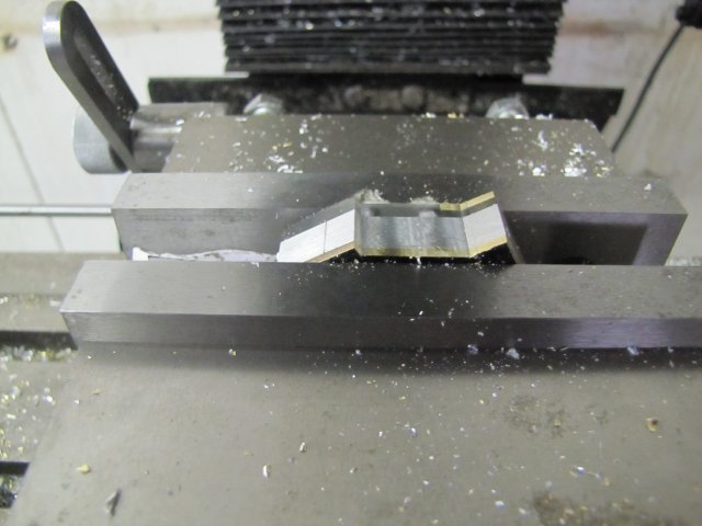
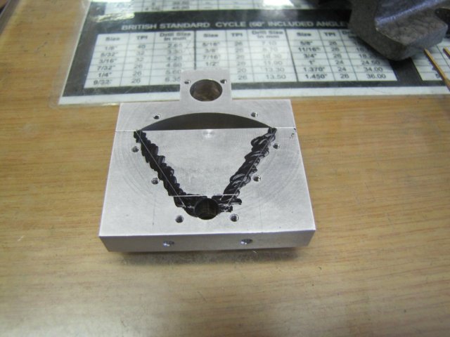
Finally I ended up with this:

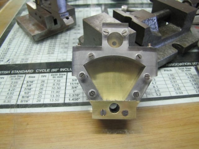
I left the outer edges of the block slightly thicker than the plans show - they are purely cosmetic, and the extra thickness is to help prevent the perspex from cracking.
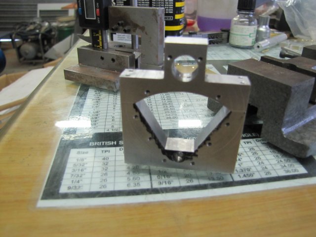
Overall progress:


 :ddb:  Looks more like it.  There's still some work left on the block - a hole to drill and tap in the top for air supply, and a bit of clearance milling on the bottom for the vane - then  a final flat-lap and cosmetic work, but the hardest part is over.

 :beer:, Arnold

Offline saw

  • Hero Member
  • *****
  • Posts: 1003
  • Country: se
  • lucky amateur
    • Svenssons AckordsWerkstad
Re: Elmer's Kimble engine
« Reply #45 on: January 29, 2012, 01:37:31 PM »
Nice build Arnold, you have done it again  :med: :med: :med:
_________________________
Greetings / Benni
http://myprojecty.wordpress.com/category/steam-engine/

Rob.Wilson

  • Guest
Re: Elmer's Kimble engine
« Reply #46 on: January 30, 2012, 05:22:38 PM »
Clever bit of machining Arnold  :clap: :clap: :clap: :clap:

Looks like it going to  be another fine engine, mumble mumble    :coffee:


Rob  :)

Sometimes rapping a bit lead strip around a boring bar ,about 1/2" from the cutting end  helps dampen out vibration

Offline sbwhart

  • Global Moderator
  • Hero Member
  • *****
  • Posts: 3530
  • Country: gb
  • Smile, Be Happy, Have Fun and Rock Until you Drop
Re: Elmer's Kimble engine
« Reply #47 on: January 30, 2012, 05:47:57 PM »
Fine bit of machining Arnold you're certainly not getting into a flap with this one

  :lol: :lol: :lol: :lol:

Looking forward to the next instalment  :clap: :clap: :clap: :clap: :clap:

A little bit of clearance never got in the road
 :wave:

Location:- Crewe Cheshire

Offline DaveH

  • Hero Member
  • *****
  • Posts: 1413
  • Country: za
  • Kempton Park, South Africa
Re: Elmer's Kimble engine
« Reply #48 on: February 03, 2012, 12:57:41 PM »
Arnold,

Looking very smart :clap: :thumbup:
 :beer:
DaveH
(Ex Leicester, Thurmaston, Ashby De La Zouch.)

Offline arnoldb

  • Hero Member
  • *****
  • Posts: 515
  • Country: na
  • Windhoek, Namibia
Re: Elmer's Kimble engine
« Reply #49 on: February 04, 2012, 10:45:43 AM »
 :beer: Thanks Benni

Rob , Cheers mate  :beer::lol: I'm giving you a chance to catch up.   :thumbup: Aye - I know about wrapping the lead around, but I didn't have any suitable handy.  I just have bug chunks of it (mostly in my butt  :palm:) and very thin (0.8mm) soldering wire... 

 :beer: Thanks Stew -  :lol: :lol:  - Hopefully the next installment will be in by tomorrow evening  :dremel:

Dave, Thanks  :beer:

 :Doh: No shop today...  Had to do "Work" work...

 :beer:, Arnold