Author Topic: Elmer's Kimble engine  (Read 51983 times)

Offline arnoldb

  • Hero Member
  • *****
  • Posts: 515
  • Country: na
  • Windhoek, Namibia
Re: Elmer's Kimble engine
« Reply #50 on: February 05, 2012, 12:41:10 PM »
 :doh: My work life has been keeping me pretty busy of late, so shop time is hard to come by.

This afternoon I drilled a 2.5mm hole through the center of the engine top:

That was tapped M3 for the air inlet.

I next milled out the excess metal that was still left on the bottom of the engine:


The bottom mounting holes were not tapped yet, so I also tapped those M3, and gave the block a final flat-lap on both sides.  That pretty much completes the engine block part of the build.

Next I started on the vane; I milled a section of 4.8mmx12 brass flat bar down width of 9.65mm - that's the same thickness as the engine block.  I didn't quite get it, and ended up at 9.7mm.  I wanted the vane 0.01mm thinner than the engine block, so I sat down and flat-lapped it down to 9.64mm on some 600 grit paper, frequently checking with a micrometer that I was keeping it parallel and not lapping one end down more than the other.  Quite a bit of manual work, but it turned out well in the end:


Next I faced the one end square, cut it of just over length (the bit of flat bar was more than twice too long), and then squared up the other end as well.  The vane top needs a slot where a seal with a small spring will be installed, so I started cutting that with a 2mm cutter.  after about the 7th pass, a bit of a disaster; just a second of inattention and I increased the rate of feed just too much:

Oh well, that poor end mill has been doing duty for more than six months now, in everything from plastic to a bit in stainless; it was getting a bit blunt.  So I fetched a new one from my stock and finished the job.  There's only one left now, so it's time I fired off an order to RichOn - I need some other cutters as well...

Back when I started this project, I mentioned the fact that Elmer's plans has a measurement error with the mortise and tenon joint.  I was still undecided whether I was going to use this method for joining the vane to the main shaft. 
This joint is most likely the weakest link in the engine, and would see quite a bit of torque transferred through it, so just soft-soldering the vane to the shaft without some form of additional strengthening would very likely lead to failure.
Many moons ago, John Bogs suggested that silver soldering the joint would be his way to do it - I agree, but then there's one teeny little problem for me; this joint has to be done ultra-neat as any excess would be very difficult to clean up, and that's something I'm still having problems with when silver soldering.
So it was either the mortise and tenon for me, or I had to find another solution.  I did the latter, and decided that three pieces of 1.5mm piano wire running between the shaft and vane would be just as strong - if not stronger than - a mortise and tenon made from brass.  The main loading on the joint is radially, and the wire would cope well with that - while loctite would be more than adequate to keep things from coming apart.

I drilled three 1.5mm holes spaced 2.5mm apart in the bottom of the vane:


Next I cut a section of 6mm silver steel to length (  :dremel: I restocked earlier this week) and cleaned it up on the lathe.  Then I drilled matching 1.5mm holes in it - offset to compensate for the one thicker cylinder cover so that the ends sticking out from the engine would be equal:


I used the Dremel with a cut-off wheel to slice off three sections of 1.5mm music wire, and pressed those into the vane with some loctite, and with more dabs of loctite, pressed the lot into the shaft.  The middle hole on the shaft had wandered a tiny bit, but this actually helped things;  I had to use the mill vise to press it together the last bit - and the vise aided in getting everything nice and square.  It won't come apart easily, but if needed, I can get it apart again with some heat.  Some of the excess loctite running between the two pieces also help to make the seal air tight:

and


A quick assembly, and things are looking good; some oil smeared on the vane gets distributed evenly everywhere on both the rear and front covers, and there's no binding  :ddb::

 :beer:, Arnold

Rob.Wilson

  • Guest
Re: Elmer's Kimble engine
« Reply #51 on: February 05, 2012, 03:41:35 PM »
Lookin Great Arnold  :clap: :clap: :clap: :clap:

Looks like it will be a runner soon  :headbang:

Rob

PS those parts look friggin small  :palm:

Offline doubleboost

  • Madmodder Committee
  • Hero Member
  • *****
  • Posts: 1619
  • Country: gb
  • Newcastle Upon Tyne
Re: Elmer's Kimble engine
« Reply #52 on: February 05, 2012, 05:18:59 PM »
Like Rob said friggin small :bugeye: :bugeye:
Beautifully proportioned though :thumbup: :thumbup:
Once i get below m6 i start to worry :lol: :lol: :lol: :lol:
John

Offline Stilldrillin

  • Global Moderator
  • Hero Member
  • *****
  • Posts: 4972
  • Country: gb
  • Staveley, Derbyshire. England.
Re: Elmer's Kimble engine
« Reply #53 on: February 06, 2012, 04:00:58 AM »
Arnold.
I've been sitting here, scratchin' me head for the past few weeks. Wondering what all those unfamiliar parts would add up to. :scratch:

But, now I've got it!! I think.....  :D

Nice, different project, and well shown.  :clap: :thumbup:

David D
David.

Still drilling holes... Sometimes, in the right place!

Still modifying bits of metal... Occasionally, making an improvement!

Offline DaveH

  • Hero Member
  • *****
  • Posts: 1413
  • Country: za
  • Kempton Park, South Africa
Re: Elmer's Kimble engine
« Reply #54 on: February 06, 2012, 09:32:59 AM »
Arnold.

Coming along just dandy  :thumbup: :thumbup: :thumbup:

Well shown as usual. :clap: :clap: :clap:

 :beer:
DaveH
(Ex Leicester, Thurmaston, Ashby De La Zouch.)

Offline arnoldb

  • Hero Member
  • *****
  • Posts: 515
  • Country: na
  • Windhoek, Namibia
Re: Elmer's Kimble engine
« Reply #55 on: February 11, 2012, 02:05:07 PM »
 :beer: Rob, thanks mate.  I'm a wee bit slow on this one though  :palm: - still a lot left to do. 

Thanks John  :beer::lol: it might be a tad small; there's some 10BA coming up soon as well... M6 is HUGE  :lol: :lol:
(Rob very kindly sent me the 10BA taps and a die 2 years ago - must have been too small for him too...  :lol: - Rob, Thanks mate  :bow: - just joking! ) 

 :beer: Cheers David.  Sorry for puzzling you  :palm: - but I'm glad you're getting it.  I hope when I'm done with this one, it should be easy for anybody to understand  :thumbup:

Thanks very much Dave  :beer:

Got to the rotary valve today.  The plans for the valve itself is a separate chapter in Elmer's book.
I went about making it quite differently from the way Elmer describes - in fact, I did not do a single bit of marking out...

As I'd made slight dimensional changes to the engine block in the valve area to suit my available reamers, I had to re-calculate some of the dimensions of the valve.  Most importantly, it's slightly bigger at a close 10mm fit compared to the 3/8" (9.53mm) the plans call for.  This meant that some of the porting cut-outs had to be slightly deeper than those shown on the plans - all by 0.235mm ~ 0.24mm.  The 1/8" shaft section was re-sized to a running fit for 3mm.

First I turned down a bit of 1/2" brass rod.  An 8mm long section 2.98 mm thick to match the 3mm reamed hole in the the back engine cover and the next section 9.99mm thick for a close fit in the reamed 10mm hole the engine top:

  :ddb: I got a nice smooth finish just turning to size, so no lapping needed here.

Off to the mill with the dividing head mounted in the vise, and the edge finder and hand-wheel zero-rings used to locate things - from this point, all operations were done according to mill dial readings:


The valve needs a 1.6mm hole drilled accurately through it's center, but on one side, the hole is connected to a 2.4mm slot.  Rather than have the drill bit wandering on a curved surface, I first milled the slot, and then drilled the hole - much easier this way:


Another small change to Elmer's design follows - this time to correct a booboo that crept in when I drilled the port holes in the engine top; the drill wandered a bit on both holes, and they are pretty far off axially compared to the valve center line.  The original valve design uses just the 1.6mm through-hole to supply air to the ports in the engine top - meaning everything have to align pretty darn accurately, and I don't have that...  So to compensate, I milled a short slot 1.6mm deep axially on the other side of the workpiece (rotated 180o since the last operation):

After milling the slot in the photo above with a 1.5mm cutter, I followed it with a 2mm cutter - which might be a mistake...  I'll see if this is OK later.

The exhaust cut-outs followed - taking care to cut them both from the correct side; one had to be done feeding in on Y, and the other feeding out on Y:


Back to the lathe, and parting off - an action photo for a change:


The finished valve:


Well... not quite.  Seeing as I have this one transparent engine cover, and one of the most difficult things to explain to people when they're looking at my little engines is always how and where the air or steam goes inside the invisible bits of the engine, I decided to add a cross-section of the valve cut-outs on the "visible" face of the valve.  I just free-hand milled this lot with a 1.5mm cutter 0.1mm deep:

The 1.6mm drill bit sticking through there is what I used to estimate level and orientation when I clamped up the workpiece  :lol:

With the milled out bits on the valve face coloured in with a permanent pen, it'll look like this in the engine top:


 :beer:, Arnold

Offline foozer

  • Full Member
  • ***
  • Posts: 194
  • Camano Island WA
Re: Elmer's Kimble engine
« Reply #56 on: February 11, 2012, 03:34:04 PM »
Them pieces are getting kinda small, with my handful of thumbs, heh heh heh

Looking good

Robert
Ignorance is Bliss, thus I aim for Perfection

Offline saw

  • Hero Member
  • *****
  • Posts: 1003
  • Country: se
  • lucky amateur
    • Svenssons AckordsWerkstad
Re: Elmer's Kimble engine
« Reply #57 on: February 11, 2012, 07:40:17 PM »
Wow  :clap: :clap: :clap: :clap: :clap:
_________________________
Greetings / Benni
http://myprojecty.wordpress.com/category/steam-engine/

Offline arnoldb

  • Hero Member
  • *****
  • Posts: 515
  • Country: na
  • Windhoek, Namibia
Re: Elmer's Kimble engine
« Reply #58 on: February 12, 2012, 12:07:25 PM »
Thanks Robert  & Benni :beer:

Today's little bit, the eccentric.  It's not a difficult part to make at all - in fact all the difficult bits of the engine are now done - but once again I made a slight change to it. 
If made as per plans, the eccentric is bolted to the flywheel, and when the engine is assembled, the eccentric ring is retained between the flywheel and the bearing column. 
I don't want the eccentric ring to touch the bearing column when the engine is done, simply because the column will be painted, and the ring will either rub off the paint, or the paint will add quite a bit of friction while running - or both. 
So I decided to add a step to the eccentric and eccentric ring to prevent that.  The ring will still run against the flywheel on one side, but that's OK, as the flywheel won't be painted. 
I'm also going to make the eccentric ring a split assembly rather than one piece.  This is mostly for ease of assembly; this engine will be finicky to assemble when done, so I'd rather do a bit of extra work up front.  It will also add some visual appeal - I hope.

Started turning up the eccentric - a bit of 20mm silver steel turned down to 17.5mm, and a 1mm long step turned down to 16.5mm diameter:


Off to the mill and mounted on the rotary table - purely for the fact that it's easy to center the RT to the spindle, plonk the chuck on it and dial in the hole locations.  The two holes needed drilled - the most important one is the 6mm hole on the right, as that determines the eccentric offset. The hole on the left is 2.5mm - that will be transferred to the flywheel and then drilled out to 3mm:


Back to the lathe with the chuck, and parting off at thickness:

It looks like the lathe is running hell-for-leather in that photo, but actually, it's only running at 110rpm - I can't do much faster than that on parting steel.  The lathe's spindle bearings is a bit worn, and I have a load of backlash on the cross slide feed nut as well.  To top that lot, the "parting" blade I'm using is actually a HSS wood plane cutter that I ground down, and anything faster than that on steel would just toast the cutting edge.  Not to mention the fact that this was an interrupted parting cut because of the two holes in there   :coffee:

Once parted off, I spent some time and energy to file away the tool marks on the parted face, thereafter a bit of rubbing on emery, and the parted side of the eccentric is all nice and shiny.  Shoved a bit of 6mm silver steel through it and the flywheel, and clamped the lot together with a toolmaker's clamp, and then clamped the clamp in the mill vise and transferred the 2.5mm hole into the flywheel - taking care not to have the hole exit on the other side of the flywheel:


Off to the drill press, and with the same toolmaker's clamp trick, opened up the 2.5mm hole in the eccentric to 3mm, and countersunk it for a nice fit for some 3mm countersink screws I have:


Next I tapped the hole in the flywheel to M3, shortened one of the M3 countersink screws for a proper fit, and this is what it looks like assembled together:


 :beer:, Arnold

Offline DaveH

  • Hero Member
  • *****
  • Posts: 1413
  • Country: za
  • Kempton Park, South Africa
Re: Elmer's Kimble engine
« Reply #59 on: February 14, 2012, 09:39:08 AM »
Excellent Arnold  :thumbup: :clap:

This is going to be a smasher :bow:
 :beer:
DaveH
(Ex Leicester, Thurmaston, Ashby De La Zouch.)

Offline arnoldb

  • Hero Member
  • *****
  • Posts: 515
  • Country: na
  • Windhoek, Namibia
Re: Elmer's Kimble engine
« Reply #60 on: February 18, 2012, 09:30:50 PM »
Thanks Dave  :beer: :beer:

A bit more progress; this is turning into a weekends-only project it seems...

With all the hard-to-do parts done, I don't know how long the yet-to-be-made parts will take to do, but soon I'll have to start assembling bits and pieces to see if everything fits.  The base and sub-base picked up a bit of rust earlier on, and there were a couple of dings in them as well.  The dings were my own fault - I didn't follow the rules of scrupulously cleaning the mill vise each time a part was moved, and some swarf got trapped and made dents.

So first I cleaned up the dings - had to lightly mill away the sides of both the base and sub base to get rid of them:


Then I set to with a file and some scotch-brite to remove the last major machining marks and all the rust from the bits, and gave them a coat of primer:


In the previous post I mentioned I might make the eccentric ring a split one, so I grabbed a bit of 3mm brass plate and roughly laid it out:


After picturing the finished part in my mind on the completed engine, I decided against making the split eccentric ring; it would look a bit "chunky" against the rest of the engine.  The smallest taps and screws I have are 10BA, and even If I used these to close the eccentric ring, I'd have to turn down their heads just to fit, and they'd still look overly large.
I do have 1.4mm taps, but no die nut, and if I want to single-point turn screws for these, I first have to make some tools, which have to wait for another day.

So, back to a simple ring for the eccentric ring, and a bit of phosphor bronze turned down to outside diameter - I nearly grabbed a bit of aluminium bronze I have for this part, but remembered in time that I had to silver solder on it!:


After a bit of drilling, and boring, things were to size, with the step turned in to match the one I made on the eccentric:

There was nearly a brown-pants moment while drilling the bronze...  I'd forgotten I recently bought a new 10mm drill bit, and it's still very nice and sharp... It grabbed into the bronze, pulling the tailstock chuck right out of the tailstock taper.  I grabbed the old chipped 10mm drill, and roughly stoned its cutting faces to a more suitable profile for bronze and finished the job.

The eccentric fits a treat - turning closely, but smoothly in the ring, with the eccentric face _just_ protruding a bit:


Next I parted the ring off:


It was about 0.05mm too thick after parting off, so I flat-lapped that off on some emery, and ended up with this:


Elmer's plans call for 1.6mm  (1/16") plate for the valve rod and connecting rods.  I thought I had 1.6mm brass plate - well I thought wrong   :coffee:.  I have 1.2mm and 2mm.  For a while I sat debating with myself whether to maybe make the rods from round rod, but decided against that as well.  So, I'll use the 2mm plate, and I cut some strips from it:


Then trimmed the valve rod to width - 4mm in this case, leaving it about 0.02mm over size for final finishing:


I love my digital camera to bits; it takes fairly good photos without even trying hard, and it'll take 500 to 800 photos on a single full charge, but one thing I don't like about it is the fact that it'll suddenly show the low-battery-of-doom indicator, and only take two photos before shutting down completely on low battery.  The last time the batteries ran out was last year when I was finishing the second Coomber, and I didn't give the batteries a full charge...  You have three guesses what happened today, and the first two don't count.

Without photos while the batteries were recharging a bit, I silver soldered the eccentric ring to the eccentric rod, and cleaned it up a bit:

I didn't notice it in the shop; but the photo shows some interesting things colour wise.  Both the eccentric ring and flywheel rim are phosphor bronze, but of two different compositions - I say that because they behaved a bit differently while machining.  The rim has a bit of patina on it already, but is more yellow than the eccentric ring which is more copper in colour, suggesting a higher copper content in the alloy of the ring.  Next the yellow of the brass eccentric rod follows.  There's also the different grays - ranging from the darker shade of the silver steel eccentric (maybe indicative of it's high carbon content) to the zinc colour of the galvanized screw, then the aluminium approaching "white" and finally the silver sliver of high-content silver in the joint between the bronze ring and brass "rod".

Regards, Arnold

Offline cfellows

  • In Memoriam
  • Sr. Member
  • *****
  • Posts: 303
Re: Elmer's Kimble engine
« Reply #61 on: February 19, 2012, 12:58:14 AM »
Nice project, Arnold.  Wouldn't mind seeing a couple more pictures of that dividing head if you find the time...

Chuck

Offline saw

  • Hero Member
  • *****
  • Posts: 1003
  • Country: se
  • lucky amateur
    • Svenssons AckordsWerkstad
Re: Elmer's Kimble engine
« Reply #62 on: February 19, 2012, 04:56:13 AM »
Nice work as usual Arnold  :thumbup: :thumbup: :thumbup:
_________________________
Greetings / Benni
http://myprojecty.wordpress.com/category/steam-engine/

Offline arnoldb

  • Hero Member
  • *****
  • Posts: 515
  • Country: na
  • Windhoek, Namibia
Re: Elmer's Kimble engine
« Reply #63 on: February 19, 2012, 11:13:30 AM »
Thanks Chuck & Benni  :beer:

I'll post today's bit in an hour or so.

In the meantime, here you go Chuck:
Just for a bit of background...
I'ts a genuine Myford dividing head - has a 60 tooth worm wheel rather than the more common 40 tooth on most available DHs.
The separate bit in the pictures is it's own tailstock - it slides into the one open hole that can be seen in some of the photos.
The adapter plate it's mounted on at the bottom is actually a bit I made myself - it was originally a cross-slide extension piece for use on my lathe, but now it's a quick way to mount the DH in the mill vise; I plonk it down on a pair of parallels and clamp it up, and I'm good to go for "general accuracy will do" jobs.
As it has the same spindle nose as my lathe, it's very quick to unscrew the chuck from the lathe and transfer it to the DH, and I can use any of the lathe chucks or face plate on the DH to hold things.
Photos - if there's any bits you'd like more detail on or a different angle, feel free to ask:


 :beer:, Arnold

Offline arnoldb

  • Hero Member
  • *****
  • Posts: 515
  • Country: na
  • Windhoek, Namibia
Re: Elmer's Kimble engine
« Reply #64 on: February 19, 2012, 11:48:40 AM »
Today's bit - I think it's an hour or so later  :lol:

One thing I didn't do when I made the vane shaft was mill out flats on it for the vane arm setscrews - that was easily done:


Then I spent some time with the base - flattening the primer a bit with some 1200 emery, and gave everything the first coat of paint:


Next I marked out the vane arms on some brass flat bar:


And drilled and reamed the vane rod holes:


Then I sawed both bits off the parent stock, and with a bit of 6mm rod trough the holes clamped them together in a small vise, then removed the rod and clamped them up with a toolmaker's clamp that's narrower than the workpieces:


The clamp could then be clamped in the mill vise, with the bits lying flat on top, and I drilled a 2.5mm hole trough to tap M3 - this keeps the connecting rod offsets exactly the same for both vane arms:
  Elmer's plans use 2mm pins here - cross drilled for using a piece of thin wire as a retainer, but I had enough fun with that method on my Grasshopper engine; I prefer screws and bolts.

I used a bit of rod and the 2.5mm drill to keep the pieces aligned, and clamped them up in the vise so that the center line is horizontal to the vise jaws:


Then drilled the top 2.5m mto thread M3 for set screws:


While I was about it, I just tapped the holes as well:


Next I used some bits 'n bobs to get things set up to mill away the sides:


And off to the big vise to file the rounds; it takes me longer to set up something to machine curves like these than it does to just file them to the line, and where it's a cosmetic feature like here, a file's plenty good enough:


After a quick rub on emery, things look presentable:


The arms needed a bit taken off on the one face of each; rather than set up the rotary table for this, I did it on the lathe:


Arms finished:


And where they fit on the vane; I'll have to shorten the set screws a bit:


 :beer:, Arnold

Offline sbwhart

  • Global Moderator
  • Hero Member
  • *****
  • Posts: 3530
  • Country: gb
  • Smile, Be Happy, Have Fun and Rock Until you Drop
Re: Elmer's Kimble engine
« Reply #65 on: February 19, 2012, 11:48:58 AM »
This jobs comming on a storm Arnold

Top stuff

 :clap: :clap: :clap: :clap: :clap:

Stew
A little bit of clearance never got in the road
 :wave:

Location:- Crewe Cheshire

Offline Stilldrillin

  • Global Moderator
  • Hero Member
  • *****
  • Posts: 4972
  • Country: gb
  • Staveley, Derbyshire. England.
Re: Elmer's Kimble engine
« Reply #66 on: February 19, 2012, 02:53:06 PM »
Shaping up beautifully Arnold!  :clap: :clap:

I love watching you and Stew, fashion the fiddly diddly parts.......  :thumbup:

David D
David.

Still drilling holes... Sometimes, in the right place!

Still modifying bits of metal... Occasionally, making an improvement!

Offline doubleboost

  • Madmodder Committee
  • Hero Member
  • *****
  • Posts: 1619
  • Country: gb
  • Newcastle Upon Tyne
Re: Elmer's Kimble engine
« Reply #67 on: February 19, 2012, 06:19:53 PM »
Hi
Arnold
3rd from last picture very clever  :thumbup: ::do it on the lathe :clap: :clap: :clap:
Small fiddly bits :) :) :) :) perfectly formed
John

Offline DaveH

  • Hero Member
  • *****
  • Posts: 1413
  • Country: za
  • Kempton Park, South Africa
Re: Elmer's Kimble engine
« Reply #68 on: February 21, 2012, 07:41:50 AM »
Arnold,

Very nicely posted as usual  :thumbup: :clap:

Coming along very well - looking good  :thumbup: :clap:

DaveH
(Ex Leicester, Thurmaston, Ashby De La Zouch.)

Offline arnoldb

  • Hero Member
  • *****
  • Posts: 515
  • Country: na
  • Windhoek, Namibia
Re: Elmer's Kimble engine
« Reply #69 on: February 26, 2012, 01:03:38 PM »
Stew, Cheers mate  :beer:

Thanks David  :beer: I have still have a lot to learn from Stew :bow: - but the fiddly bits seems to be getting easier to make  :D

Cheers John  :beer:  - nothing clever about it though; just me being lazy  :lol: - it doesn't turn out perfect this way; just "good enough for now"  :thumbup:

Thanks Dave  :beer: - I was hoping to be a bit further along, but some "life" happened in between  :doh: :lol: :lol:


Yesterday was a dead loss in the shop; "work" work all day interfered...

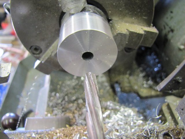
This morning I started off with the crank webs - digging through my stock I had a choice between aluminium and bronze in the approximate sizes needed.  As the flywheel web is aluminium, I decided on the aluminium to match it; all the linkages will be brass anyway, and I like a bit of contrast.  Cleaned off, and drilled and reamed to 6mm:


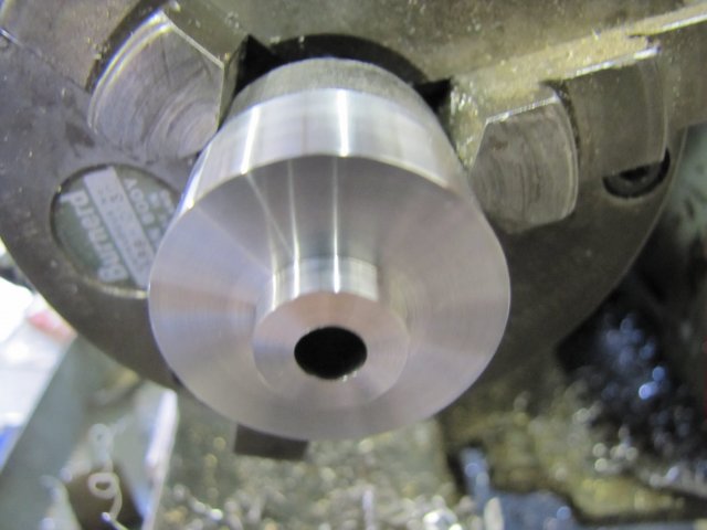
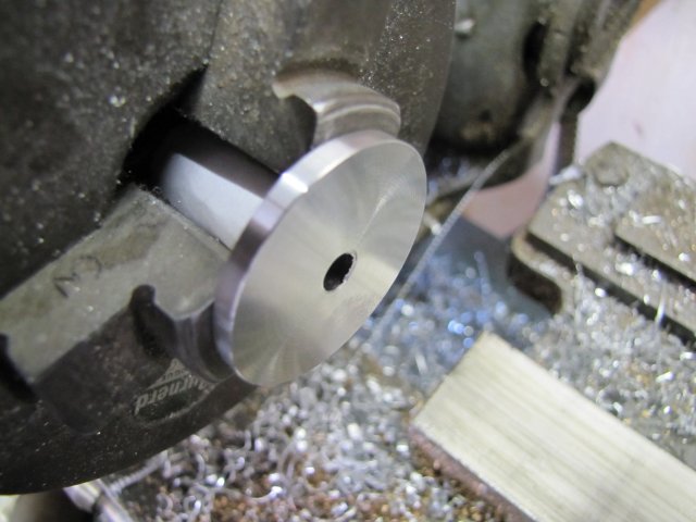
Next, turned the step on the first web:


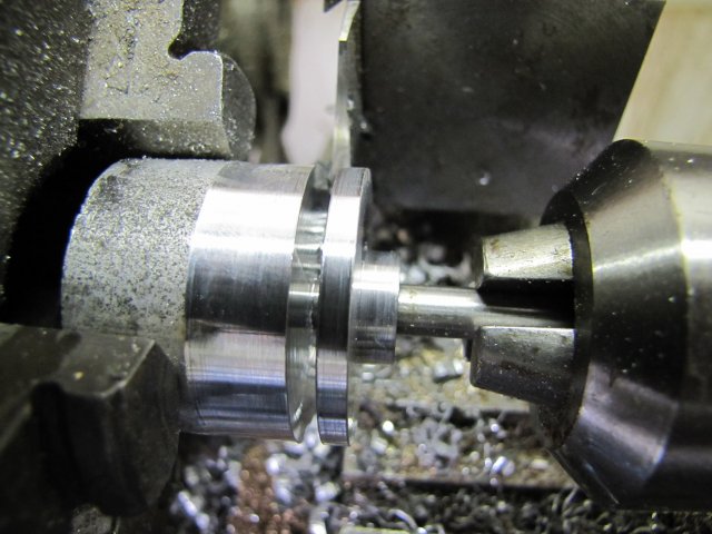
And parted of with a bit of oiled 6mm rod in the tailstock chuck to both help support and catch the web:


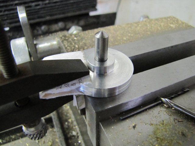
The second one followed - using the same measurements.  I'm slowly starting to get better finishes on parting cuts - it still looks horrible though - I wonder if it's possible to get a really smooth finish on a parting cut ? :

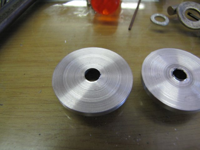
I'll just keep on trying harder   :ddb:

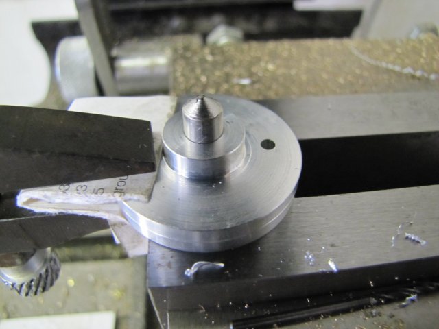
Cleaned up the ugly parting marks:


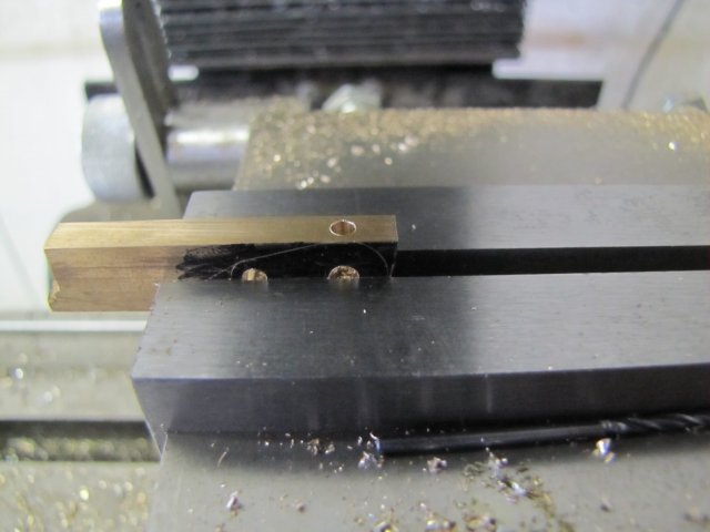
The webs must be made as a left and right-hand version, and to prevent binding on the engine later on, their crank offsets must match exactly - so I shoved a bit of rod through them held back-to-back, and clamped them together and clamped them flat on the mill vise:


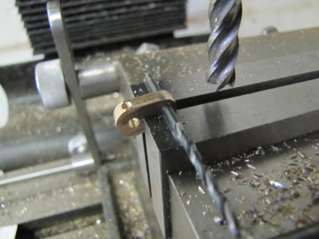
Then I used the edge finder to locate the center line in Y and also the X edge of the pin; then I just dialed in the hole position on the X handwheel - it takes a simple bit of work on a calculator to calculate   crank throw - (half the pin thickness + half the center finder thickness) and dial that in   :smart:  
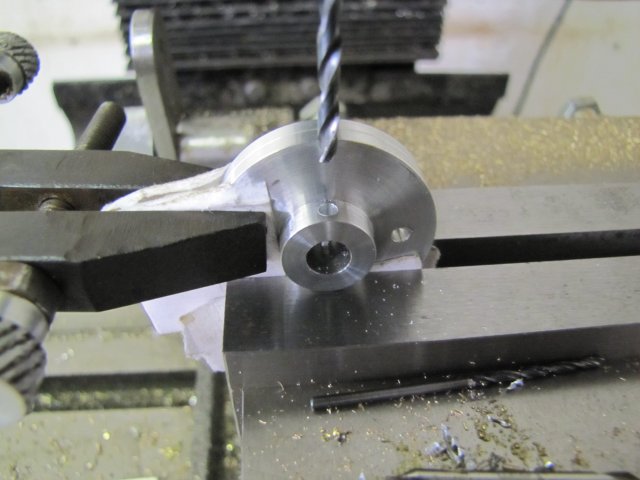
A quick spot with a center drill, and drilled a 2.5mm hole to thread M3 later:


While I was busy drilling holes, I drilled the 2.5mm holes to tap M3 for the grub screws (set screws) as well:


After sitting down and playing around with the set of M3 taps, I had the finished webs:

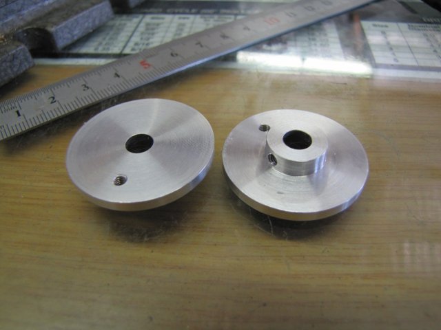
There's some scuff marks on them; those I'll remove at a later stage.

I did a bit more paint work on the columns, and COMPLETELY stuffed it up   :palm:   :bang: :hammer: :

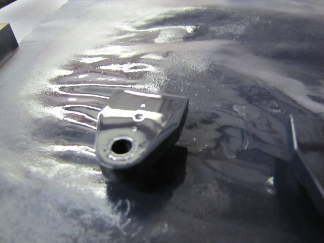
Hopelessly over-sprayed, and there must still have been some contaminants on there to boot.  As the bushes are slightly proud of the column faces, there was only one way to recover; I dunked the lot in acetone and got rid of every last vestige of paint on there, and started anew - right from primer.

While waiting for primer to dry, I started on the valve arm - pretty much the same method as the main crank arms:


Rounding over with facets before filing:


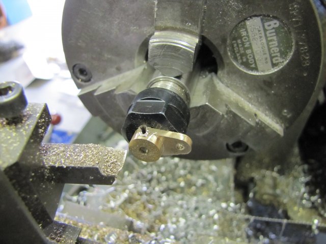
Thinning it down - I used a bit of 3mm rod chucked up in the ER11 collet chuck.  Just filed a flat on it for the grub screw to hold onto, and turned it down.  You'll see that the grub screw was a bit long, and I'd turned a bit of that away in the process as well:


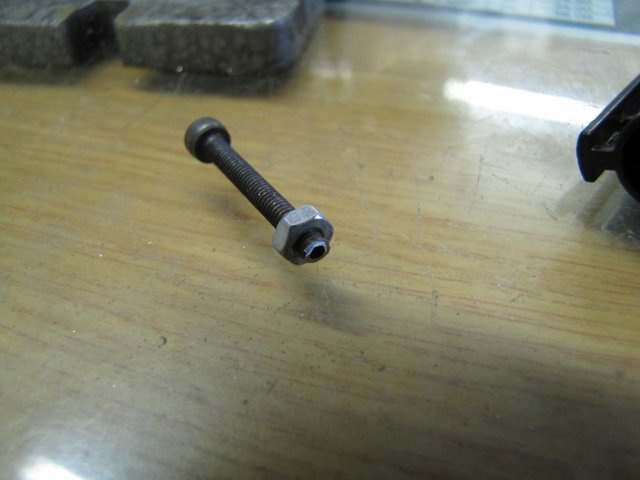
To get more use from that same grub screw , I just screwed it half-way into a 3mm nut, and with a 3mm cap screw turned in from the other end of the nut to lock up against it, I had enough to hold on to to go to the bench grinder and grind off the excess:


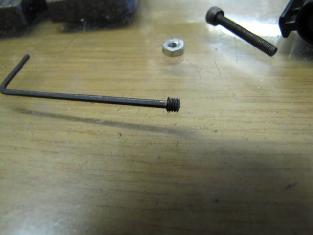
The grub screw was still a bit long, so I plonked it on the end of an Allen key and carefully ground down the other end as well to shorten it further making a slight point on the end:


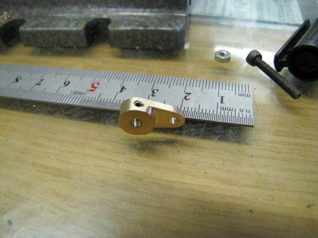
A bit of work with a fine file and emery, and the valve arm is done:


The bits left to make are getting less now, but some things depend on getting the engine assembled partly to take some measurements.  I did start to clean up the two bits of brass plate cut in an earlier post - that's the start of the connecting rods:

 :coffee: I guess I'd better start putting drill bits back in the index - before they slip into the fourth dimension.

Before I left shop for the day, I gave the offending column another coat of paint; it still does not look great, but I'll let it dry for a couple of days and give it a rub-down with some  1200 emery before a final coat of paint:


 :beer:, Arnold

Offline DaveH

  • Hero Member
  • *****
  • Posts: 1413
  • Country: za
  • Kempton Park, South Africa
Re: Elmer's Kimble engine
« Reply #70 on: February 28, 2012, 09:20:18 AM »
Arnold,

You do some excellent workmanship, it's a very pleasant learning experience to follow your posts.

Very nicely done and shown  :bow: :bow: :bow:

Thanks
 :beer:
DaveH 
(Ex Leicester, Thurmaston, Ashby De La Zouch.)

Offline arnoldb

  • Hero Member
  • *****
  • Posts: 515
  • Country: na
  • Windhoek, Namibia
Re: Elmer's Kimble engine
« Reply #71 on: March 03, 2012, 01:22:59 PM »
 :beer:  Thanks very much Dave

This afternoon I made some small bits.  As I mentioned earlier, I'm not going to use Elmer's "pin with hole and soft wire" method for retaining the connecting rods and valve rod.  So it was time to start making screws.

First up, a small screw for linking the valve rod with the valve arm.  I started with some 4mm silver steel and turned a 2.5mm step on it to match the hole in the crank arm, and then a 2mm step to thread M2:

If you look carefully at the photo, the first section of the smallest step is undersize; I'd overshot and turned it down to 1.8mm - which wouldn't do as that is too small for an adequate M2 thread.  It's great for getting an easy and straight start to the thread though  :)

After threading with the tailstock die holder, I turned off the excess 1.8mm bit, and parted of the screw.  It just needs a slot:


Next, some 5mm silver steel - turned with a 4mm and 3mm step, and threaded M3:

That was parted off, and repeated another 3 times.

If you look carefully at the previous photo, you'll notice that the 3mm thread does not run to the shoulder.  Normally, one would make an undercut there for a crank screw like this, but I'm a lazy rotter and didn't want to grind up a narrow enough cutting bit for the undercut.  Anyway, the crank rods need some slight spacing off the webs and crank arms, so I rather set about making some 0.5mm thick brass washers - ID 3mm and OD 6mm.
If one first drill the brass rod and then part off the washers, each is left with a burr on the side that must be filed down; a real pain.  So I used a method that leaves much less burrs in a case like this.
I first made all the parting cuts - leaving the core at just under 3mm.  The first section was a bit thick  ::):


Then I center drilled the end, and drilled a 1.5mm pilot hole through - the pilot hole is needed to prevent the 3mm drill from wandering around for the next step.  Then I just drilled down the lot with the 3mm drill, and all the washers are left on it with a minimum of burring:


This is what the bunch of washers look like without any clean-up whatsoever:


Next I slotted all the screws - not the ideal setup to do it with, but it worked:


For today's shop session, I ended up with this lot:


Not as much as I'd hoped to get done, but I spent about 1 1/2 hours at one point searching for my ER11 collet closer nut after dropping it, the collet that was in it and the screw that was in that  :bang: :bang: I never knew these things were made from rubber; everything bounced all over the show, and not having chameleon-like eyes it's impossible to follow the flight paths of three madly bouncing bits at the same time   :palm:
I eventually found the nut - there's an old V6 engine standing between my lathe and mill at this point, and the nut had lodged between the water pump and its pulley:

 :lol: I've found another entrance to the fourth dimension!

 :beer:, Arnold

Offline doubleboost

  • Madmodder Committee
  • Hero Member
  • *****
  • Posts: 1619
  • Country: gb
  • Newcastle Upon Tyne
Re: Elmer's Kimble engine
« Reply #72 on: March 03, 2012, 06:24:39 PM »
Hi
Arnald
Those screws are aw sum :thumbup: :thumbup: :thumbup:
Every one should have a old V6 under the bench :lol: :lol:
John

Offline arnoldb

  • Hero Member
  • *****
  • Posts: 515
  • Country: na
  • Windhoek, Namibia
Re: Elmer's Kimble engine
« Reply #73 on: March 04, 2012, 03:28:51 PM »
 :beer: Thanks John.   :lol: :lol: :lol: - That lump of Essex is standing in my way all the time; I'd better find a use for it  :lol: :lol: :lol:

Today's bit; more fiddly stuff and making screws  :loco: .

First a teaser   :borg: - I had to assemble things well enough to judge how to bend the front connecting rod, as the perspex engine cover is quite a bit thicker than the cover from the plans:


I then bent the connecting rod to match:

The back one was bent to plans, as I didn't change any measurements there.

Then I drilled the big end holes in both rods:

 :( Sorry - out of focus photo!

Next I located the hole against the vise stop and set the mill x handwheel to zero on location:


Then I dialled in the con rod length on the x axis and prepared to center drill:

After center drilling and drilling through at 4mm on the one rod, I flipped them and drilled the other.  This made sure they had exactly the same length hole-to-hole in each even though the are bent.  It's crucial to get this measurement the same for this engine.

Next I rounded over the ends with a file, and cleaned the lot up with some scotch-brite:


I turned up the main shaft, and loctited the flywheel to it before taking a bit of a lunch break - that gave enough time for the loctite to cure, as it was a nice and warm day today:


One more part required was the vane seal - I prepared some 2mm brass plate for it, and drilled a 0.8mm hole to retain the spring in it:

I need to buy some smaller drills at some point  ::)

The vane seal was then sawn off from the parent stock, and filed and lapped to size.  Elmer specifies some very thin stainless wire to make a spring from.  I don't have that, and I was thinking of using a bit of thin high "E" guitar string for that, but I couldn't find the bit I stole off the guitar - till I remembered I used it to repair the cheese slicer.  Then my eyes fell on the big wire brush, and I clipped one of it's bristles off and bent that to the spring shape - that's the thin black part in the photo:


The valve rod still needed a hole drilled and tapped M2 for connecting to the valve arm - that followed:


I'd originally intended to use some 2mm all-thread "studs" and nuts to mount the engine top to the body as I didn't have long enough M2 screws for the job, but as everything else on the engine now use slotted screws, that would look a bit out of place.  So I chucked some 4mm silver steel in the ER11 chuck, and turned it down to 1.95mm diameter 13mm long, and filed a good cone on the end to allow the M2 tailstock die to start easily  Then I turned a short section down to 3mm - that will make the screw head:

When turning down thin long sections like this, it's imperative to hone the toolbit to a very sharp edge on all cutting edges - then lathe max RPM (~640 for my Myford) and a smooth and steady hand feed to keep a consistent thin chip coming off.  Works a treat, but seems to take a bit of practice.  I need to build myself a box tool like Tel showed over on HMEM.

Thread, part off & repeat 3 more times, and I had this lot - just needs slotting:

 ::) The one on the right's head is a bit big...  I forgot to turn it down to 3mm  :lol:

Easily fixed:

I'm really starting to enjoy the ER11 collet chuck working along with my ER25 chuck like this for small jobs!

I slotted them the same way as yesterday's screws.  Next I turned up the steam connector from some 5mm hex brass:


Then I laid out all the bits and started giving them a once-over to remove the last tooling marks and to make sure everything was there:


 :beer: , Arnold

Offline saw

  • Hero Member
  • *****
  • Posts: 1003
  • Country: se
  • lucky amateur
    • Svenssons AckordsWerkstad
Re: Elmer's Kimble engine
« Reply #74 on: March 04, 2012, 06:10:37 PM »
I am so very impressed of you, you make it so very easy. Nice work  :clap: :clap:
_________________________
Greetings / Benni
http://myprojecty.wordpress.com/category/steam-engine/