Author Topic: lathe cross slide 'dishing'  (Read 38284 times)

Offline unc1esteve

  • Full Member
  • ***
  • Posts: 126
  • Country: us
lathe cross slide 'dishing'
« on: April 22, 2012, 03:10:58 PM »
On another site many people insist that all lathes are purpose built to cut a concave surface when making a facing cut.  001 dish in a 3 inch diameter.  The reason for this is always stated that it allows two cylinders to be stacked upon each other.
They quote the English writer 'Tubal Cain' as one of their resources.  They use some lathe's tolerance specifications.  No documentation, just 'that is the way it is'.
I disagree.  If this is done on purpose then the lathe would be accurate only making this one cut for this one purpose.  "Tubal Cain ends his comments by saying 'or should be', so he is expressing an opinion.  He is not a manufacturer.  I can find no lathe manufacturer's advertisement that states this as a quality of the lathe.  I have been researching lathe design on line but so far have not found any information.  I have asked several sellers of lathes if the lathes they represent are made this way but have not received answers yet.
I understand the concave theory verses the convex facing.
Does anyone have or know of documentation on this subject?
Thank you.


Offline Fergus OMore

  • Hero Member
  • *****
  • Posts: 1012
  • Country: england
Re: lathe cross slide 'dishing'
« Reply #1 on: April 22, 2012, 03:25:53 PM »
Will  Georg Schlesinger do you?
Will Martin Cleeve( K C Hart) do you?

And what about Connolly?

the stock answer is 'Ringing parts together'

I wouldn't quite knock old Tom Walshaw, he made rings around a lot of people who thought that they were also 'Men of Iron'. Get his stuff from old copies of ME and see what he had to say.
Sorry, but he came from a Nest of Singing Birds- which we don't have today.
« Last Edit: April 22, 2012, 03:51:41 PM by Fergus OMore »

Offline philf

  • Hero Member
  • *****
  • Posts: 1114
  • Country: gb
Re: lathe cross slide 'dishing'
« Reply #2 on: April 22, 2012, 03:41:00 PM »
On another site many people insist that all lathes are purpose built to cut a concave surface when making a facing cut.  001 dish in a 3 inch diameter.  The reason for this is always stated that it allows two cylinders to be stacked upon each other.
They quote the English writer 'Tubal Cain' as one of their resources.  They use some lathe's tolerance specifications.  No documentation, just 'that is the way it is'.
I disagree.  If this is done on purpose then the lathe would be accurate only making this one cut for this one purpose.  "Tubal Cain ends his comments by saying 'or should be', so he is expressing an opinion.  He is not a manufacturer.  I can find no lathe manufacturer's advertisement that states this as a quality of the lathe.  I have been researching lathe design on line but so far have not found any information.  I have asked several sellers of lathes if the lathes they represent are made this way but have not received answers yet.
I understand the concave theory verses the convex facing.
Does anyone have or know of documentation on this subject?
Thank you.

unc1esteve,

I have a copy of Testing Machine Tools by Dr. Georg Schlesinger. (Schlesinger limits are/were often quoted in machine tools specs). In it are various figures given for the lathe facing accuracy.

"For Finish Turning Lathes": "Lathe faces (hollow or concave only) within 0 to 0.02 per 300mm in dia."

"For Toolroom Lathes (Highest Degree of Accuracy)": "Lathe faces (concave only) within 0 to 0.015 per 300mm in dia."

"For Facing Lathes": "Lathe faces (concave; only for machines with headstock and carriage mounted on common baseplate) within 0 to 0.05 per 1,000mm in diam."

So, all of these are much better than 0.001" per 3" in diameter and, in all cases, they can be zero.

Hope this is of help.

Cheers.

Phil.
Phil Fern
Location: Marple, Cheshire

Offline Fergus OMore

  • Hero Member
  • *****
  • Posts: 1012
  • Country: england
Re: lathe cross slide 'dishing'
« Reply #3 on: April 22, 2012, 05:52:55 PM »
Let's be sure-- all this has absolutely nothing to do with crosslides but the concave facing is inbuilt into the headstock spindle- not the crosslide.

The crosslide doesn't need to be at 90 degrees or 3 thous in three inches or concave to a thickness of a tissue( Horner) or ability to withstand the efforts of a Churchill tank per Cleeve about Myfords to destroy the alignment.

You can chuck the whole crosslide out of the window as it is quite irrelevant for many lathe users. I have two lathe with one and one without! And so did Tom Walshaw and Cleeve and quite a few of us. I 've just got in the post from my good friend 'Miner' about epicyclic chucks mounted either fore or aft as my first reply was sent.

If we want to go off at a happy tangent, it was Cleeve that was instrumental in changing the narrow gib principle used at that time by Myford- as facing- by some of the greats on their machines was getting 'interesting'

It's ALL in Model Engineer- at some point.

Offline unc1esteve

  • Full Member
  • ***
  • Posts: 126
  • Country: us
Re: lathe cross slide 'dishing'
« Reply #4 on: April 22, 2012, 06:38:58 PM »
Thank you for the swift replies.
When I post a question I try to be as clear as possible but I seem not to succed.
I used the term cross slide because of the answers on the other site.
I am not knocking Mr. Tom D Walshaw.
I did not mention Dr. Georg Sclhesinger because I understand the difference between tolerance and error.
You say the concave is built into the head stock spindle.  This is what I am looking for.  An advertisement, article or comment from a lathe manufacture, supplier or seller that describes this.
Tolerance is accuracy.  A .001 dish is an error.  To tell a novice that this is normal to all lathes and it is for a specific reason is not good policy.


Offline Alan Haisley

  • Jr. Member
  • **
  • Posts: 65
  • Country: us
Re: lathe cross slide 'dishing'
« Reply #5 on: April 22, 2012, 08:11:01 PM »
If the head-stock spindle is twisted so that a facing cut will be concave then a chuck or collet held piece will be taper cut with the collet end larger. It's easy enough to take a light facing cut from the center out so that the outer edge of a piece stands proud of the center if that's what you want.
Alan

Offline andyf

  • In Memoriam
  • Hero Member
  • *****
  • Posts: 1795
  • Country: gb
    • The Warco WM180 Lathe - Modifications
Re: lathe cross slide 'dishing'
« Reply #6 on: April 22, 2012, 08:50:30 PM »
I think I agree with you, Alan. If a lathe turns true cylinders rather than slight tapers, its spindle must be parallel with the bed. If the same lathe produces concavities or convexities when the cross-slide is used to make facing cuts, it seems to me that the likely cause is that the dovetail on top of the saddle is not perpendicular to the bed and the spindle axis.

Facing cuts on my Chinese lathe produce far more concavity than they should, and with a largish square held against the saddle dovetail, the Mk 1 human eyeball reveals the cause. If I ever find a 55 degree dovetail cutter at a reasonable price, I'll fix it. Too much metal needs to come off for a scraper to be used, other than for finishing off after the miller has done the hard work.

Andy
Sale, Cheshire
I've cut the end off it twice, but it's still too short

Offline Fergus OMore

  • Hero Member
  • *****
  • Posts: 1012
  • Country: england
Re: lathe cross slide 'dishing'
« Reply #7 on: April 23, 2012, 03:20:16 AM »
Gentlemen,
                  What you have forgotten( or I think that you have forgotten) is that a lathe is NOT a trignometrical figure. It is relatively a weak piece of equipment which will bend on cutting loads. If one creates a lathe to follow a pure rectangular shape, the cutting forces will create a convex shape. It then that this 'rocking about like a pea on a drum' of two convex faces occurs.

Clearly, I have little or no experience of what happens on Andy's lathe but I suspect that much of the problem lies in the lathe being flimsy.

Am I wrong? Well someone in a distant and nigh forgotten past wrote of what happened  when he stuck his elbow on the tail stock( bored rigid) during a long cut. Again, Thomas wrote at length about the subject in MEWM and earlier in ME. Tom Walshaw wrote extensively on the subject of lack of rigidity and his lathes constantly having to be adjusted - because of earth movement- in his retirement. Again, he wrote of problems of flatness in single point milling and filled Model Engineer with comments from people- who hadn't his maths skills :smart:

However- and it is worth thinking about- I 'did' the history of a chief draughtsman of a then very successful machine tool works. He left a few mediocre watercolours of a few lodges, a church and a couple of Scottish scenes and an engraved silver cigarette case.

In real money, it probably amounts to enough cash to fill a car with fuel-- and his wonderful business is - poof- gone- like him.

Offline philf

  • Hero Member
  • *****
  • Posts: 1114
  • Country: gb
Re: lathe cross slide 'dishing'
« Reply #8 on: April 23, 2012, 05:56:36 AM »
Thank you for the swift replies.
When I post a question I try to be as clear as possible but I seem not to succed.
I used the term cross slide because of the answers on the other site.
I am not knocking Mr. Tom D Walshaw.
I did not mention Dr. Georg Sclhesinger because I understand the difference between tolerance and error.
You say the concave is built into the head stock spindle.  This is what I am looking for.  An advertisement, article or comment from a lathe manufacture, supplier or seller that describes this.
Tolerance is accuracy.  A .001 dish is an error.  To tell a novice that this is normal to all lathes and it is for a specific reason is not good policy.

unc1esteve,

Rather than specifying individual figures for a machine tool the manufacturers usually mention the standard to which they are made.

This is the test certificate which came with my lathe. There are two sets of figures for most parameters - one for the Industrial Quality (mine) and one for the Toolroom Quality version. Actual figures aren't quoted - just that they passed the individual test.


The particular test for Cross Slide perpendicularity to the Spindle Axis (11) has a typo in the metric version, showing 0.15mm instead of 0.015 (the Imperial version is correct at 0.0006").

You will see 4 standards mentioned, ISO, DIN, ASA & Schlesinger.

Is this the sort of information you're looking for?

Sorry Fergus - there are tolerances for the perpendicularity of the cross slide as well as the parallelism of the spindle to the carriage and, incidentally, in Machine Tool Reconditioning, Conelly says "Axis of the headstock spindle to be parallel to the outside ways of the bed in the vertical and horizontal planes". For a Toolroom Lathe a tolerance is given of 0 to +/- 0.0003" over 12" - not unidirectional (although Schlesinger does specify a unidirectional tolerance). Conelly specifies that the cross slide should have a unilateral tolerance of the squareness of it's travel to the axis of the headstock - for Toolroom Lathes 0 to 0.0005" over 12" diameter hollow or concave only.

Cheers.

Phil.
« Last Edit: July 13, 2017, 02:38:55 PM by philf »
Phil Fern
Location: Marple, Cheshire

Offline bp

  • Full Member
  • ***
  • Posts: 119
Re: lathe cross slide 'dishing'
« Reply #9 on: April 23, 2012, 07:08:50 AM »
To me as a simple ex draftsman used to applying tolerances, all of this indicates that the machine tool design fraternity considered that a flat face was very important, a convex face was very bad news and a (slightly) concave face was acceptable.  The degree of concavity determining whether the machine will be designated "Toolroom" or "Industrial".
cheers
Bill Pudney

Offline BillTodd

  • Hero Member
  • *****
  • Posts: 1099
  • Country: 00
  • Colchester Essex (where the lathes were made)
Re: lathe cross slide 'dishing'
« Reply #10 on: April 23, 2012, 07:25:41 AM »
Quote
On another site many people insist that all lathes are purpose built to cut a concave surface when making a facing cut.
They are misinterpreting the tolerance specification.

The target for a tolerance is always zero, normally this is in the middle of the tolerance band i.e. if something is spec'ed for 10mm  +/- 0.1mm then you'd aim for 10.000mm. However, some items must absolutely not be over or under size (like a bearing fit) , so specifications are +0/-X or +X/-0 .

The tolerance for a lathe for facing as previously mentioned is  +x/-0 (concave) . The ideal lathe has 0 concave and 0 convex, but is allowed to be slightly concave by to meet specification.

This means the lathe manufacturer , balancing the need for accuracy against the cost of production, will often play safe and leave the machine with a slight concave rather than do the extra work to get it right.

Bill

[edit] BP beat me to it  - The Bill's are right again  :thumbup:
Bill

Offline philf

  • Hero Member
  • *****
  • Posts: 1114
  • Country: gb
Re: lathe cross slide 'dishing'
« Reply #11 on: April 23, 2012, 07:32:17 AM »
To me as a simple ex draftsman used to applying tolerances, all of this indicates that the machine tool design fraternity considered that a flat face was very important, a convex face was very bad news and a (slightly) concave face was acceptable.  The degree of concavity determining whether the machine will be designated "Toolroom" or "Industrial".
cheers
Bill Pudney

Bill, you may be a "Simple Ex Draftsman" but you have summed the facts up nicely!  :thumbup: (Not so simple after all!)  :lol:

I spent 38+ years in mechanical design - starting as a student apprentice when there were 40+ drawing boards and draftsmen/ design engineers in our office and retiring 3 years ago when there were no drawing boards left and only me doing any mechanical design on CAD. I never missed the drawing board. I still have several sets of drawing instruments which will never be used again - just too nice to throw away.

 :beer:

Phil.
Phil Fern
Location: Marple, Cheshire

Offline unc1esteve

  • Full Member
  • ***
  • Posts: 126
  • Country: us
Re: lathe cross slide 'dishing'
« Reply #12 on: April 23, 2012, 01:13:14 PM »

I am sorry I do not have the communication skills to convey what I was looking for.  Here are some edited quotes from the '7 x 12 mini lathe forum'.

 1.  'Does anyone have an explanation as to why I always get a "dishing" effect on a work surface mounted in the 4-jaw chuck or on the faceplate, quite noticeable on anything bigger than an inch across?The edges come out slightly higher than the middle, like a saucer.'

 2.  'I faced a 3" diam aluminum and got very good finished until I checked for
 flatness. I placed a straight edge on the face and the middle section is
 dished. There is light able to shine in the middle.'

 3.  'I then used the cross-slide to wind the DTI in along the straight edge for 2", until it reached the centre-line. The DTI reading increased by 0.008" over those two inches, which is rather more than a nominal amount. '
 
Answers

 1.  'The concave is made on purpose, common to all lathes, so that two cylinders will stack on to of each other and not rock.'

 2.  'Your lathe is OK. Go, replenish the earth, and subdue your worries.'

 3.  'But a slightly concave face is considered the norm, generally speaking. Just is.'

I do not have the equipment to measure .0005 in 12 inches to see how much light will shine under a straight edge.  I feel that being able to see light under a straight edge in one inch or .008 in two inches is not a tolerance common to all lathes.  These are errors.

To believe that these errors are purpose built into all lathes just so we can stack up two cylinders is believing in a fairy tale.  To tell a novice that their lathe is ok is poor practice.  How are we novices to become craftsmen if given this kind of incorrect information?

What I was looking for was something from a lathe manufacturer to confirm these statements.  Is not the target of a tolerance 'zero'?  In my mind these tolerances contradict these statements. 

Lathes are not designed to face a concave surface but to face as close to 'zero' as possible.  These gentlemen are just not correct.

Offline BillTodd

  • Hero Member
  • *****
  • Posts: 1099
  • Country: 00
  • Colchester Essex (where the lathes were made)
Re: lathe cross slide 'dishing'
« Reply #13 on: April 23, 2012, 02:15:38 PM »
Somewhere on this site is a long thread in which Bogstandard explains how he fixed up a friend's mini lathe. You could do worse than read through that :)

[edit] here it is, the most popular thread in this section:

http://madmodder.net/index.php?topic=627.0
Bill

Offline Alan Haisley

  • Jr. Member
  • **
  • Posts: 65
  • Country: us
Re: lathe cross slide 'dishing'
« Reply #14 on: April 23, 2012, 02:18:53 PM »
It's obvious to me that the reported effect of the cutting followed by the measuring means that either the lathe spindle has enough play that under load it moves or the headstock itself has play that causes the same thing. i.e., the lathe in question is either not solid enough to avoid the headstock twisting under load or the spindle or headstock itself has some play that shows up under load. Since the DTI measurement won't place a significant load it shows the "twist".
The message originator might try orienting the cutter so that the right edge is parallel to the spindle and taking extremely light cuts. If they do that, I would predict that the finished facing cut will show less dishing. This would be consistent with what I think is happening.
Perhaps someone with more experience than I can come up with a method to isolate the movement and  remove as much of it as possible.
Alan

Offline Fergus OMore

  • Hero Member
  • *****
  • Posts: 1012
  • Country: england
Re: lathe cross slide 'dishing'
« Reply #15 on: April 23, 2012, 03:28:13 PM »
I think that following some very learned remarks on this, it would be prudent for Uncle Steve to tell us initially what lathe is giving rise to such concern, what tools and accuracy he has at his disposal  and what the results have been given on his machine- at this moment.

I am sure that I will not be the only correspondent here who will read the results with keen interest.

Offline Jonny

  • Hero Member
  • *****
  • Posts: 780
Re: lathe cross slide 'dishing'
« Reply #16 on: April 23, 2012, 04:59:40 PM »
Quite right Alan and the Bills, spot on.

Too much reading bull and not enough doing springs to mind. We had a saying at work a little knowledge is dangerous.

Heres a link to Harrison users site where the dimension of max permissable runout is stated. 0.01mm over 300mm! Machine came off at 0.002mm runout, hence the term runout not concave or convex, thats impossible unless play in slides or head.
Putting two and two together the term mislead 'concave' is actually a straight edge erring on the side of +90 degrees like a cone, big difference.

http://f1.grp.yahoofs.com/v1/wLSVT8xVkrxA6JOvDGXYf4_Zm-I3es3ErB6yneQAUmYEKbcNu69UZQvenQ_XfgnNLG-PuTltUxPgzz4GkvCgox4LFLEc30cYhVqJpWG08-Nqpro/Z1.%20VS%20330TR%20Accuracy%20Chart/C.%20Harrison%20Accuracy%20Chart%20-%20VS%20330TR

Offline philf

  • Hero Member
  • *****
  • Posts: 1114
  • Country: gb
Re: lathe cross slide 'dishing'
« Reply #17 on: April 23, 2012, 06:12:55 PM »
Quite right Alan and the Bills, spot on.

Too much reading bull and not enough doing springs to mind. We had a saying at work a little knowledge is dangerous.

Heres a link to Harrison users site where the dimension of max permissable runout is stated. 0.01mm over 300mm! Machine came off at 0.002mm runout, hence the term runout not concave or convex, thats impossible unless play in slides or head.
Putting two and two together the term mislead 'concave' is actually a straight edge erring on the side of +90 degrees like a cone, big difference.

http://f1.grp.yahoofs.com/v1/wLSVT8xVkrxA6JOvDGXYf4_Zm-I3es3ErB6yneQAUmYEKbcNu69UZQvenQ_XfgnNLG-PuTltUxPgzz4GkvCgox4LFLEc30cYhVqJpWG08-Nqpro/Z1.%20VS%20330TR%20Accuracy%20Chart/C.%20Harrison%20Accuracy%20Chart%20-%20VS%20330TR

Jonny,

OK, concave may be slightly misleading in that it may infer a radius and you are correct when you say that the error will produce a cone :thumbup: ....... but, to me, describing it as concave is better than describing it as a cone which could be (for want of better words) "concave" or "convex". The term concave is used in more than one machine tool standard or reference.

My turn to be pedantic now - the Harrison test sheet describes the 0.002mm as deviation from squareness and not runout. Runout is used correctly at G8 - "Run-out of spindle nose centre" where the spindle is rotated and the dial gauge is fixed.

Take, for example, a faceplate faced on the same Harrison lathe without removing it - the runout (with the gauge fixed in the toolpost and the spindle rotated) would be zero (or very near to zero). If the gauge was traversed across the faceplate from the outside (operator) towards the centre it should also show a zero deviation - that is until it gets past the centre when the gauge will start to show the deviation from flat.

As Bill said - in an ideal world everything would be exactly parallel or perpendicular or concentric etc. etc. but manufacturing costs would be unreasonably high - hence working to tolerances and why there are various classes of tolerance for different classes of machine.

 :beer:

Phil.

Phil Fern
Location: Marple, Cheshire

Offline loply

  • Sr. Member
  • ****
  • Posts: 260
Re: lathe cross slide 'dishing'
« Reply #18 on: April 24, 2012, 09:01:10 AM »
I have always been under the impression, and it seems logical, that the perpendicularity of a facing cut is controlled by the perpendicularity of the cross slide dove tails.

Misalignment of the head will ofcourse create the same effect (a convex or concave face), but we have to assume that's not the case.

A poor lathe may have a cross slide which is not perpendicular and will create a convex or concave face even if the head is properly aligned.

Clearly a convex face is going to be a major problem in most situations, whereas a convex one (if it's only slight) is likely to be more tolerable.

Offline Lew_Merrick_PE

  • Hero Member
  • *****
  • Posts: 690
  • Country: us
Re: lathe cross slide 'dishing'
« Reply #19 on: April 24, 2012, 10:55:56 AM »
Back in the dark ages when I was attending University, the Mechanical Engineering department was peopled with Asian and Arabic students to a high degree.  One of those students ended up working for the Indian Ministry of Industry.  In the late-1980's and early1990's he got into the habit of sending me development machine tools to evaluate for him as he was unsure how often the "analysis" he got from his own people was more of the make the boss happy variety than clear, honest fact variety.  Among the things sent to me this way was an original pilot product unit of what is now the Chinese 7X blah lathe sold by many import/dealers.  It was quite nice right out of the box.  Yes, I spent no small amount of time making adjustments, but once they were made, I could turn an 8 inch long part and have it true and round within .0004 FIM.

Fast forward a few years when the 7X blah lathes from China started appearing.  One that sticks in my mind had the axis of the spindle out of true to the bed by more than .010 in 4 inches!  That one was the worst, but I have never had one brought to me where the spindle was true to the bed to a degree that I would accept.  Now, to be honest, I usually one see ones that people are having real problems with -- so this may be an unfair statement.  However, I would argue that the first thing one should do with these 7X blah Chinese lathes is to check the spindle alignment!

I happen to own a MT3 gage bar.  One can be made reasonably at fairly low cost using a MT3 tool holder of appropriate size (I typically use ř.500) with an appropriate length of mating drill rod (silver steel).  Access to another MT3 capable spindle to verify the concentricity of the set-up is in order, but that is usually not that hard to find in a local machine shop -- and shop owners are usually understanding about such needs (at least in my experience).

There is really not a lot one can do to fix problems with a lathe (7X blah or whatever) until you have the spindle aligned to the bed!

Offline Jonny

  • Hero Member
  • *****
  • Posts: 780
Re: lathe cross slide 'dishing'
« Reply #20 on: April 24, 2012, 03:48:24 PM »
My turn to be pedantic now - the Harrison test sheet describes the 0.002mm as deviation from squareness and not runout.  Phil.

Perfectly correct Phil, i stand corrected :palm:

Offline unc1esteve

  • Full Member
  • ***
  • Posts: 126
  • Country: us
Re: lathe cross slide 'dishing'
« Reply #21 on: April 26, 2012, 07:24:05 AM »
Conclusion

Thank you all for your responses.

 1.  I need to improve the way I communicate my ideas.  I repeat myself.
I was looking for documentation to prove or disprove the statement that 'all lathes were made a certain way on purpose, and the reason why they are made this way.  I received several answers from sellers of lathes.  One said yes, one said no, and two thought I was asking for help on how to machine a radius and suggested I purchase a radius tool.

 2.  The word concave as used here is misleading as it refers to a curve or radius.
Jonny's use of a straight line erring is much more accurate.  Also a facing cut is a straight cut at 90 degrees, not a curved surface.

 3.  I used the term 'cross slide' because of the answers on the other site.
Many suggested the problem of the 'dishing' is caused by the cross slide and commented how difficult it would be to correct the slide.  I disagree, it is not caused by the cross slide.  As Lew Merrick said the spindle must be aligned with the bed first.  Bogstandard showed it can be done with shims under the head.

 4.  Many do not understand the difference between tolerance and error.
A lathe is not designed to face a curve so we can stack cylinders.  It is designed to cut straight lines.  It is designed to face a 90 degree angle within a tolerance.  Were the lathe built with this error on purpose the this would be the only accurate cut.

 5.  The authors mentioned suggest to me that I am correct. 
Even though they use the word concave they are talking about a straight line of 90 degrees with a very small tolerance of less than 90 degrees over a long distance.  .001 in one inch, .008 in three inches are not tolerances but errors.  To suggest that all lathes are constructed this way is not correct.

 6.  If a concave or dish were the accepted norm the specifications would read +X/+X, or -X/-X.

 7.  The test certificate by Philf shows this if it is read correctly.

 8.  The mini lathe site talks about all of the errors built into the smaller machines but the only one they accept as not an error is the dishing problem.  The dishing problem and then the cross slide problems can be corrected by Bogstandard's methods.

 9.  I am not making tests on my equipment.  I was looking for documentation to prove or disprove other people's remarks.

10.  I feel that when a novice is astute enough to recognize his equipment is not functioning correctly it is poor practice to tell him a fairy tale.  We novices need to be taught correctly.


Offline Jonny

  • Hero Member
  • *****
  • Posts: 780
Re: lathe cross slide 'dishing'
« Reply #22 on: April 26, 2012, 05:05:40 PM »
I think this thread and links from it may be the definative answer regardless of what writers have written.

I think the answer you are looking for is in Phils and my link to Harrison owners site.
I feel its absolute bull what has been written else where, the error/runout on a facing cut is purely acceptable to makers tolerances nothing else.

Right who got a test sheet for a Smart and Brown or Dean Smith and Grace to prove the point.

Offline unc1esteve

  • Full Member
  • ***
  • Posts: 126
  • Country: us
Re: lathe cross slide 'dishing'
« Reply #23 on: April 26, 2012, 05:33:37 PM »
Jonny, I was not going to post again but I was not able to see the Harrison link.  I get a 'not found' message.

Offline bp

  • Full Member
  • ***
  • Posts: 119
Re: lathe cross slide 'dishing'
« Reply #24 on: April 27, 2012, 01:02:13 AM »
A couple of minor points,
1  "Concave" does not infer/imply/suggest that the concavity follows a radius.  It simply means that the high points are on the outside and the low points are on the inside (think of a cave).  How the inside and outside points are joined up is relatively unimportant in the meaning of "concave".  In the case of a faced plane (hopefully!) the concavity will be conical.  It could be chewed out by a hungry woodpecker and still be concave, but unlikely to be generated on a machine tool.
2  I would bet that any test sheet from Hardinge, Smart & Brown, Schaublin (plus whoever else you care to mention)  would show an acceptable deviation in flatness, or concavity.  I would also bet that the deviation would be somewhat less that that shown by other manufacturers, such as that shown above.

Sorry if this can be categorised as fairytaleism
cheers
Bill Pudney

Offline steamer

  • Jr. Member
  • **
  • Posts: 86
  • Country: us
Re: lathe cross slide 'dishing'
« Reply #25 on: June 03, 2012, 12:55:00 PM »
If the perfect lathe was perfectly rigid, a working tolerance would be superfluous...we would strive for perfect geometry to compliment the perfect rigidity.  All the parts made on the perfectly rigid perfectly aligned lathe,....would be perfect.

We don't live in a perfect world though do we..

Concave facing allows a part fixed to a faceplate to bear on the outside diameter.  A very stable condition!    Otherwise if the part was convex, it would only bear on the center and perhaps 1 line along the side of the cone so generated.   A very unstable condition.

Draw the figures for yourself...you will see what I mean.....and as a side note, at the tolerance levels we're talking about, whether it's conical or spherical ...well it's REAL hard to tell.

Additionally as a facing cut is put on a large diameter part, more axial deflection will occur the farther from center that the tool cuts.   A concave (conical or spherical)  initial condition will counter that to some extent. That's just physics....no material is infinitely rigid....to some small extent, everything is made of rubber...lathes and work pieces alike. The machining process is just not completely deterministic......This can be frustrating, but don't let "perfect" get in the way of "good".  There's still lots of good parts that can be made on our compromised and imperfect lathes

Dave
"Mister M'Andrew, don't you think steam spoils romance at sea?"
Damned ijjit!

Offline Davo J

  • Sr. Member
  • ****
  • Posts: 475
  • Country: au
Re: lathe cross slide 'dishing'
« Reply #26 on: June 04, 2012, 11:09:45 AM »
Your lathe sounds like it's out a lot. I think the manufacturers allow a bit of concave to allow for wear over the years. If it was dead on any wear would meant your parts wouldn't seat properly.

Dave

Offline Miner

  • Full Member
  • ***
  • Posts: 176
  • Country: ca
Re: lathe cross slide 'dishing'
« Reply #27 on: August 07, 2012, 03:59:18 PM »
This is a fairly old thread, but I thought I'd throw a few extra comments into it. Obviously concave is much better than convex for the reasons already mentioned. You could even readjust, scrape, re-shim everything into dead true, or at least as well as your best indicator would allow you to achieve a flat surface. Except!!!!, just like Davo and maybe others have mentioned, that wouldn't last very long at all due to the way cutting tool pressures would wear the cross slide dovetails. Even the very tight clearances on brand new high end lathes that allow the slide to move at all will show as a deflection at the cutting tool tip. So if everything was adjusted to allow a dead flat facing cut to be taken, and taking into account that deflection. It wouldn't take very long or very much wear and you would then have a lathe that faced convex. So another reason the lathe manufacter's set them up to face concave is to allow them to wear in towards flat. This is the same idea and reason why a lot of tail stock center lines are set slightly high on most good lathes.

It's also quite easy to accurately measure just how much any lathe is out from a dead true facing cut. It does require a good dependable .0001 reading DTI that will give accurate and repeatable readings. Probably for the most of us, the lathes faceplate would be the the logical item to use. Just take a fine faceing cut across it till it fully cleans up. Using a DTI with the indicator tip on the faceplate and moving it across the faceplate from the O.D. towards the center, or going in the opposite direction from the C/L out towards you just like the facing cut was done will tell you less than nothing. Your just duplicating what the facing tool did.  That's not how it's done. You indicate from the face plate C/L to the face plates outer rim farthest away from you. The reading you then get will be TWICE the actual deviation from true flat. Normally a lever type DTI isn't all that accurate for a distance measurement. But for the small deflections you should be seeing, it should be ok.

I'd also caution anyone making this test to not assume the headstock is out of alignment if they get higher indicator readings for concave or convex than they'd like. Those readings could easily be and probably are a cross slide wear or alignment issue. The less you pay for a lathe or the older it is then the more chance there is of it being a cross slide problem.

It's a bit OT to the thread, but if you are going to run this test? Then you may as well test the headstock bearings at the same time. Just take a fine clean up cut on the face plates O.D. and then setup the indicators tip on the face plates OD farthest away from you. To make it a bit clearer, if the cutting tool cut the face plates rim at the 9 0'clock position your going to set the indicators tip at the 3 o'clock position. Slowly rotate the face plate 360 degrees by hand, and the deviation from zero you see will again be twice the amount of what the actual out of round condition is.

Pete

Offline andyf

  • In Memoriam
  • Hero Member
  • *****
  • Posts: 1795
  • Country: gb
    • The Warco WM180 Lathe - Modifications
Re: lathe cross slide 'dishing'
« Reply #28 on: August 13, 2012, 04:35:32 PM »
Thanks for that exposition, Pete. As I mentioned in this thread back in April, facing cuts on my Chinese lathe are far more dished than is acceptable, and I have just applied your method of establishing just how bad things are. Not wanting to end up with a badly dished faceplate, I chucked up a 85mm OD, 50mm long lump of cast iron, and used that, taking each cut with the saddle locked, the topslide gibs tightened and the tool held in the original "4-way" toolpost rather than my QCTP, all for maximum rigidity.

Both a finger DTI and a plunger type used from the centre to the far side both indicated a variation of 0.27mm over 40mm; as you said, that needs to be halved, giving 0.135mm dishing over 40mm. The dovetail on top of my saddle is 160mm long, so both sides of the dovetail would need to be skimmed in a sort of wedge shape to a depth (on the headstock side) of virtually nothing at the front to 160/40 x 0.135 = 0.54mm at the back and vice versa on the tailstock side. Actually, 0.45 or 0.50mm would probably be safer, leaving a bit of concavity but definitely avoiding convex facing, which would leave me worse off than I am now.

0.5mm is too much to take off using my meagre scraping skills, particularly inside a dovetail. I thought my dovetails might be the 55° sometimes favoured by the Chinese, but they are 60°. I have procured a good quality 60° cutter, and was thinking of milling the dovetails down, then scraping to final fit. Before doing that, it would obviously be wise to ensure the mill is trammed properly, and that the saddle is of consistent depth with no warp.

Do folk more knowledgeable than me (that would include just about all Madmodders) think this might work, if done carefully?

I have made dovetails before but only little ones on extra holders for my QCTP and the like, where there wasn't much at stake; nothing crucial like this proposal.

Andy
Sale, Cheshire
I've cut the end off it twice, but it's still too short

Offline Miner

  • Full Member
  • ***
  • Posts: 176
  • Country: ca
Re: lathe cross slide 'dishing'
« Reply #29 on: August 13, 2012, 08:05:00 PM »
Andy,
Your more than welcome. Depending on your own perceptions of machine tool alignments and what's normally posted on forums like this. It can be humerous or more than a bit frustrating. I certainly don't and never will know even half of what I'd like to about this subject alone. But you do need to run at least one more test before you go any further. And it's going to be a bit tough to keep this even somewhat short.

Your lathe bed needs to be properly leveled first. No I'm not about to get into exactly why 90% of what's normally posted about that "lathe leveling" is wrong. But it is, and most don't understand that it's only a starting point.

But you need to get your lathe bed leveled as accurately as possible with the most accurate machinist's level you can find, buy, borrow, beg, or steal. That puts your lathe bed into an "almost" neutral cutting condition. That's your starting point. You'll now need a fairly large diameter bar of free machining material. Aluminum, brass, or leaded steel would be best. The material length sticking out past the lathe chuck should be no more than 3 times it's diameter. Obviously the larger the diameter is, then the longer it can be, and the more accurate and finer your test results will be. You have to test the headstock alignment before you start remachining or scrapeing anything to be sure you don't in fact have a headstock alignment issue.

Best case? I'd shoot for something like 3" plus in diameter and say 6" plus long, yes that's a 2-1 ratio. But it's also more dependable and your not pushing the limits. So you start out with a leveled lathe bed in that neutral condition, then with that bar sticking out of the lathes chuck and WITHOUT tailstock support. You then make cutting passes till the bar is fully machined around it's OD and from it's outer end and all the way up to the lathe chuck. Your last clean up pass should be with a freshly sharpened tool, or a brand new carbide tip and an ultra fine depth of cut so your not putting any heavy stress into the part your cutting. Use a really good micrometer and get a good accurate OD dimension on the outboard end, and as close to the chuck as you can get. This will give you the results of how well aligned your headstock is to the lathe bed. This test IS NOT optional. You have to know exactly what you have before you start any remachining for alignment. Ideally both measurements should be exactly the same. That shows that the headstock C/L is in line and looking dead straight down the lathe bed.


Yes the numbers you've obtained so far are way more than they should be. Excessivly so, You do need to run the above test and figure out 100% for sure where that misalignment really is. I can't stress this enough. It could even be a combination of a headstock and cross slide alignment.

My apologys for using imperial measurements, but it's what I'm used to and my brain can easily visulise. It's my understanding that higher end precision industrial lathes are always set up with the headstock dead true to the lathes bedways. Depending on the exact description of that lathe as it's being built as just a standard or a higher end toolroom lathe, the cross slide is always purposely ground and scraped on a inward bias. Your parts are or should be always faced concave. I'm only going by what I've read. Standard lathes allow up to .001 concave over a 12" diameter. Toolroom lathes should be around .0005 concave over that 12". I have read a few items that don't conform to those exact standards, so I just can't give you a hard number.

If your headstock does prove to be true? Then the only place it can be out is the cross slide dovetails. Your test numbers so far do show something is way out of alignment. But to be honest, proper dependable test numbers do require the largest diameter you can swing. This isn't the place to cut corners and still obtain the correct test results you want. If it were me? I'd fasten a heavy plate of aluminum to your faceplate and again make that test cut I detailed in my previous post. Idealy you want the largest diameter your lathe can swing and takeing into account the usable low rpm your lathe is capable of.

You did an excellent job of setting your lathe up with a few precautions I neglected to mention trying to shorten things up a bit, so you've obviously got a good idea of what's involved.

With some good accurate test numbers under actual cutting conditions and using the largest diameter material that's practical, you should then be able to set up your parts in a properly trammed mill, and if your cross slide is the part that's defective? You should be able to set it up and remachine it well within what's needed to do the final scrapeing to the alignment specs. you decide on.

I'll be the first one to admit that all of the above is a huge long drawn out PITA, but there really aren't any short cuts. My last two posts are a prime reason why I've always thought you should buy the very best and most accurate and dependable metrology equipment you can afford. I own a variety of Chinese, Taiwan, Austrian and North American built machine tools. None of them are even close to the worlds best. I have had my Austrian built lathe adjusted to turn parrellel to less than .0002 over almost 12". It won't maintain that over even a 5 degree temperature change. But it does show what's possible even with relitively cheap home shop equipment. But if you can't measure it? You can't adjust it.

For sure I'd really like to know what your final results are though.

One more hint? The more you understand about all this, the more diligent you'll be about keeping machine tool slides clean and over lubricated. My slovenly habits really got an abrupt change after reading the Connelly book Machine Tool Reconditioning.

Pete


Offline Fergus OMore

  • Hero Member
  • *****
  • Posts: 1012
  • Country: england
Re: lathe cross slide 'dishing'
« Reply #30 on: August 14, 2012, 08:55:01 AM »
Andy, Before you start on the heroics of taking off metal, why not simplify it by putting some on?

As far as I can see it- and I don't know your lathe or whatever, you can add Turcite or Moglice or perhaps on of the other 'goos' or metal filled plastic fillers. My Myford has a Turcited saddle to fill the damage of centuries- well, years of misuse. There is nothing cheap and nasty about it, it is professionally done.

So using the same idea, you can slightly build up the saddle edges  to remove much of the concavity.

Millions of years ago or a little less, there was an article in ME about building up a vee way lathe bed with shimstock in the worn bit. The grinding was done but only on the newly applied metal shim.

Contray to Pete( sorry old friend) Connolly never had the use of modern plastics. I'm thinking that more available Devcon  might be suitable and I have certainly been surprised with Loctite660.

If all fails, you are no worse off.

Cheers

Norm

Offline Miner

  • Full Member
  • ***
  • Posts: 176
  • Country: ca
Re: lathe cross slide 'dishing'
« Reply #31 on: August 14, 2012, 02:40:06 PM »
As per usual Norman has given a great example of another direction you can go. And he's certainly quite correct about the modern moglice type materials aren't mentioned in that Connelly book since it was written, or at least it's latest up date was in the 1950's. But I don't know of anything that is up to date that covers what that book does.

There was a thread started last year? on either this forum or on the HMEM forum where the poster was doing a full rebuild on a Chinese hobby grade lathe using exactly what Norman has mentioned along with precision scrapeing for correct alignments. . Sorry I don't have a link for that thread. Maybe someone else remembers it? I was more than a little impressed with that posters work and results though.

Pete

Offline Jonny

  • Hero Member
  • *****
  • Posts: 780
Re: lathe cross slide 'dishing'
« Reply #32 on: August 14, 2012, 03:07:49 PM »
Great advice on above two posts but just to confirm milling the slides will work fine when 3 dimensionally clocked up.

At the time i was a non working partner in such a business and gave all the bits to the chief grinder as a foreigner. Had the saddle milled on my ML7 after giving it a little bit for a couple of weeks, the rest was ground first class except the bed.

Have seen Turcite on jobs, usually hinge pins that cant be removed. Cant confirm whether they last after though.

Offline Fergus OMore

  • Hero Member
  • *****
  • Posts: 1012
  • Country: england
Re: lathe cross slide 'dishing'
« Reply #33 on: August 14, 2012, 03:34:19 PM »
Whilst still quite poorly( Pneumonia) I can say that I clearly recall a Moglice write up in Model Engineers Workshop. Again, Moglice do seem to have a website but I DO have a favourites entry for Devcon products. Adding a bit to Jonny's remarks, I bought an old Myford Super 7B and paid Ł250  about 18 months ago for the bed  to be professionally reground and got a build up in Turcite for the underneath of the saddle.

Earlier still, I 'did up' a Super7 and filled the worn number 1 shear with a Loctite metal filler.
Again, I wrote up a doing up of a friends ML7 using a locally available  Lumsden grinder which Blancharded. Somewhere in Model Engineer I think.

Rambling on somewhat, I recall that the late Martin Cleeve added a extra front and rear gib to a ML7 and someone said that Myford had adopted the change from the narrow gib principle.
Certainly, Jack Radford wrote up his modifications to his Super7.

So armed with a decent scraper -ex an old file and a dollop of perhaps Devcon or Loctite it should be possible to make small adjustments- without causing damage.

Enough, I'm repeating myself and need to kill the rest of my 'bugs'.

Enjoy, eh?

Norm

Offline andyf

  • In Memoriam
  • Hero Member
  • *****
  • Posts: 1795
  • Country: gb
    • The Warco WM180 Lathe - Modifications
Re: lathe cross slide 'dishing'
« Reply #34 on: August 16, 2012, 07:19:43 PM »
Thanks, chaps. You have given me a lot of  :scratch: , hence the delay.

As to checking headstock alignment, all I have ever done is to use "Rollie's Dad's Method". Now, I appreciate that RDM can't distinguish between a misaligned headstock and a bed which is warped, but readings and the associated mathematics done at 1" intervals down an 8” test bar showed deviation of zero near the chuck increasing in regular steps to something like 0.0008" at the far end, which I reckoned wasn’t too bad for a Chinese 7x12. It is a somewhat heavier and more robust machine than the usual Seig and Real Bull versions, but even they have a reputation for stiffness having regard to their dimensions (something to do with Young’s Modulus) when compared to “real” lathes, to the extent that they seem to operate satisfactorily sitting on their on their rubber feet.

At any rate, I’m not going to risk doing more harm than good by trying to correct less than a thou over 8”. And chucking up a 3” diameter, 6” long bar as Pete suggests might cause spindle droop on a little lathe like mine; it would weigh around 12lb. But I do have some 2” OD thick walled steel tube so could try it with 4” of that to save weight.

The Moglice (or similar) idea has its attractions. It was shown in Stefan’s thread here http://madmodder.net/index.php/topic,6990.0.html where he was giving a larger version of my lathe a good going over. He didn’t mention using it for the cross slide, but did use it on his topslide dovetail. He used an accurate straightedge with a 60° bevel along it to press against the Moglice while it set, and there could be difficulties setting one of those up on one side of the dovetail so it would tweak the angle round by about 0.18° (about 11 minutes of arc), and then setting up again to get the other side of the dovetail parallel to the first. I’ll think about it, but it might be hard to accomplish.

Milling (followed by scraping) might be easier to set up. A true round bar could be tucked into one side of the dovetail and a parallel placed against the bar. Then, with a DTI held in the spindle and its finger bearing on the outside edge of the parallel, the position of the cross slide on the mill table could be adjusted so the clock showed the required amount of deviation.

Still giving it a lot of thought rather than getting on with the job, and any further input would be welcome.

Andy
Sale, Cheshire
I've cut the end off it twice, but it's still too short

Offline Miner

  • Full Member
  • ***
  • Posts: 176
  • Country: ca
Re: lathe cross slide 'dishing'
« Reply #35 on: August 17, 2012, 09:17:59 AM »
Hi Andy,
You found the exact thread of Stefang's I was thinking of. There's a lot of great tips in that thread. And that pipe you have should work real well for running a proper test. At less than .001 taper in 8", it's looking like you can pinpoint the major problem area as being in the cross slide dovetail. Even remachining it without hand scrapeing would get you a lot closer that it is now.

Once your problem is corrected, you may want to check the tailstock also. My C-6 had the tailstock pointing uphill .009" over 2". It was useless the way it was.

Pete

Offline andyf

  • In Memoriam
  • Hero Member
  • *****
  • Posts: 1795
  • Country: gb
    • The Warco WM180 Lathe - Modifications
Re: lathe cross slide 'dishing'
« Reply #36 on: August 17, 2012, 01:24:19 PM »
You keep  :poke: ing me to do more tests, Pete  :)

But at least the tailstock one was easy to do; I've just tried it. Over 2", it points skyward by just under 0.0005", which ain't too bad. Not as good on a horizontal test, though. It is aiming to the left, by a smidgeon over 0.0015". That can probably be dealt with by shifting the top casting slightly relative to the base, though the trick will be to tighten it up so it ends up both parallel to the centre-line and without any offset.

Andy
Sale, Cheshire
I've cut the end off it twice, but it's still too short

Offline Miner

  • Full Member
  • ***
  • Posts: 176
  • Country: ca
Re: lathe cross slide 'dishing'
« Reply #37 on: August 17, 2012, 02:49:56 PM »
LOL, my apology's Andy. But the more I've learned about this, then the less I take for granted. Mistakes in manufacturing, or checks that get missed can and do happen on even the very best and most expensive top quality machine tools. You really do have to run your own full set of Slessinger? (spelling?) tests. Norman of course knows the correct spelling. And as you've already learned, running these tests can tell you things that you'd really rather not know.

One more tip. And I got severly burned on this one. A good DTI doesn't weigh very much at all, and they are about the best way to measure that your tailstock morse taper bore is correct and centered in alignment to the spindle C/L for both vertical and horizontal alignment while being hand rotated from the lathe spindle if you don't have a Burke co-axe indicator. BUT!!! you would be amazed just how much those light weight DTI's can flex even a 3/8" steel rod when their extended out from the headstock spindle. The difference between the top and bottom reading while swinging that DTI around is amazing to see. I fought with my tailstock vertical adjustment for a few hours till I finally realised I was actualy seeing the effects of gravity. Having to read that reversed DTI reading in a mirror in certain positions doesn't help either. You may already know about that, but I figured it was worth mentioning. But that vertical alignment has far less importance than the horizontal one does as long as your tailstock barrel is correct like yours is. Within a very few thou should be ok. Ideally, zero/zero would obviously be the best.

I am more than a bit happy that you started this thread though. Sadly there's far too much misinformation about "proper" machine tool alignment posted on all the hobbiest forums.

There are some real experts who are very knowledable about this that could easily find fault with my rather poor understanding about this subject.

Pete

Offline andyf

  • In Memoriam
  • Hero Member
  • *****
  • Posts: 1795
  • Country: gb
    • The Warco WM180 Lathe - Modifications
Re: lathe cross slide 'dishing'
« Reply #38 on: August 17, 2012, 03:24:35 PM »
I didn't start this thead, Pete - unclesteve did, and I seem to have hijacked it. I hope he doesn't mind, but he hasn't posted on it for nearly four months.

Thankls for the tailstock advice; I'll certainly follow it when I get to the tailstock. The measurements I made were on the outside of the tailstock ram, so are no help in establishing whether its internal taper is in line. I haven't got a co-ax indicator, only a normal DTI. I suppose the best way to minimise the effect of gravity would be to put my boring head in the spindle and hold the DTI in it so the size of circle described by its finger can be adjusted. If the taper isn't true, then I'll have to shell out for a Morse taper reamer.

By the time you've finished with me, I'll need to mortgage the house  :lol:
(Why am I laughing?  :( - that's better.)

Andy
Sale, Cheshire
I've cut the end off it twice, but it's still too short

Offline Miner

  • Full Member
  • ***
  • Posts: 176
  • Country: ca
Re: lathe cross slide 'dishing'
« Reply #39 on: August 17, 2012, 07:24:23 PM »
OK then my apology's to Uncle Steve. However it worked out, it was and is a good thread. And I really can't see where anyone would think you've hijacked it.

Nope, forget the MT reamer unless yours is in bad shape as far as being scored, or it was originally machined to a poor holding taper. All it will do is follow pretty well what you already have. And it takes only a very few .001's of MT reaming and you could very easilly get into the range where a standard MT taper might not fit correctly for something like a drill chuck, or the male taper could bottom out inside before it's fully seated. Even with a machine MT reamer, I'd still turn it lightly by finger pressure alone to just clean up any internal burrs on a unhardened MT. You really don't want to do any actual cutting if possible. If you do need to recut that MT taper? A good MT reamer isn't the place to try and pinch pennies. Buy the best you can afford.

They do make MT test bars, but good hardened and ground examples so their accurate to very low tolerances are pretty expensive. I own a couple of them that were built in the U.K. To be honest? They aren't quite as useful as I thought they would be despite the comman perception that they can be used for accurately checking headstock alignments. Standard affordable lathes that most of us can actualy buy usualy have a fairly inaccurate alignment of the internal MT against the O.D. and headstock bearings. And even one speck of airborne dust could be more than enough inside that headstock taper to throw your results out. I've yet to check any headstock taper that was truely concentric with the spindle rotation anyway. Maybe Myford or better lathe owners don't have that problem? With a spotlessly clean and correct taper? They can be useful as a check for just how straight the head or tailstock bores are.

Checking the outer I.D. along with as far as you can get inside with a DTI should give you a good general idea if everyting is straight on the MT headstock & tailstock tapers without a MT test bar though.

You also should run a few general checks with the tailstock barrel extended and retracted along with being locked and unlocked.

This as a hobby for most of us I think, and we are using relitivly cheaper machine tools, So I guess we shouldn't expect perfection. But if you don't test and understand where the inaccuracys are, then there's no hope of compensating for, or with luck correcting them if or when it's needed. And for anyone else reading this? if you've never done machine tool alignment checks like this, You will learn and start to understand a lot.

But it's also these types of alignment checks that have reinforced my thoughts about buying any lathe that doesn't have or come with a test certificate. Without that, it really doesn't matter to a dealer how inaccurate any machine tool is built. My C-6 would instantly break the tips off any center drill I used with the factory machined alignment. My less than poor dealer who is no longer in business wasn't too concerned about that problem.

Pete

Offline andyf

  • In Memoriam
  • Hero Member
  • *****
  • Posts: 1795
  • Country: gb
    • The Warco WM180 Lathe - Modifications
Re: lathe cross slide 'dishing'
« Reply #40 on: August 17, 2012, 08:24:51 PM »
Funny you should mention test certs, Pete. My lathe actually came with one. They only measured the exterior of the tailstock quill, rather than its internal taper. In the vertical plane, the results are about the same as those I just made , but they are half a thou better in the horizonal.

Getting back to the main theme, there's no box on the test sheet to be filled in for perpendicularity of cross slide to spindle axis. I think I can guess why!

Andy
Sale, Cheshire
I've cut the end off it twice, but it's still too short

Offline Miner

  • Full Member
  • ***
  • Posts: 176
  • Country: ca
Re: lathe cross slide 'dishing'
« Reply #41 on: August 17, 2012, 08:43:04 PM »
Uhh, Depending on what side of the ownership coin your on, your statement is funny/not so funny, and your obviously correct about your conclusions.

My one and only lathe I've ever bought that did come with a proper test certificate has tested out slightly better than the factory written test results. I'd guess from me takeing much more time and possibly using better test equipment than the factory did. :scratch:

Pete

Offline Jonny

  • Hero Member
  • *****
  • Posts: 780
Re: lathe cross slide 'dishing'
« Reply #42 on: August 29, 2012, 02:44:33 PM »
Just come across the site for turcite
http://www.moglice.com/index.php

So, where do you get it from in small quantities?
What would be the best for a quill.

Offline Miner

  • Full Member
  • ***
  • Posts: 176
  • Country: ca
Re: lathe cross slide 'dishing'
« Reply #43 on: August 29, 2012, 04:03:57 PM »
Jonny,
There's a thread running right now on the HSM forum about Turcite and Rulon that you might want to read. Due to Moglice's composition, I'm not sure I'd use it to support a spindle or quill. I know far less about all this than I'd like to, but maybe line boring oversize and at the correct alignments and then sleeveing the oversize bore with bronze or cast iron might be better? I've read of a few people doing this while rebuilding lathes, and they had a good internal combustion engine rebuild shop precision hone the sleeved bore to fit a reground tailstock spindle.

Pete

Offline Jonny

  • Hero Member
  • *****
  • Posts: 780
Re: lathe cross slide 'dishing'
« Reply #44 on: August 30, 2012, 07:11:59 AM »
Thanks Pete, just thought it might get me out of the proverbial but too much hassle, so looks like seeking out a Bridgeport now.

Offline Miner

  • Full Member
  • ***
  • Posts: 176
  • Country: ca
Re: lathe cross slide 'dishing'
« Reply #45 on: August 30, 2012, 11:48:22 AM »
Jonny,
Your welcome, but I kind of feel like I've spoiled your day. There's a lot of people far more knowledgeable about this than myself. Maybe start a thread about what your exact problems are? Somebody here just may come up with a simple solution.

Pete

Offline bp

  • Full Member
  • ***
  • Posts: 119
Re: lathe cross slide 'dishing'
« Reply #46 on: August 30, 2012, 09:09:36 PM »
When I had to work for a living, I was involved in changing the focus of a workshop from predominently manual machines to CNC machines.  One of the biggest step changes was when we got three Bridgeport VMC1000s when they were made in Leicester.  They had (I think it was) Turcite on the X and Y axis slides, and the factory was very proud of the 24 hours of hand scraping on each machine.  In their day, the mid nineties, the B'port machines were excellent value and performance.  When I retired in 2008 we still had the three machines and they were going well.
cheers
Bill Pudney

Offline andyf

  • In Memoriam
  • Hero Member
  • *****
  • Posts: 1795
  • Country: gb
    • The Warco WM180 Lathe - Modifications
Re: lathe cross slide 'dishing'
« Reply #47 on: September 24, 2012, 06:19:25 AM »
 Well, I seem to have dealt with my cross-slide, and have got the excessive dishing (0.35mm/0.0053” dip in the middle of an 80mm/3.15” workpiece) down to about 0.02mm/0.001”. As I said earlier, I didn’t want to get too near perfection for fear of going too far and ending up with convex facing cuts.

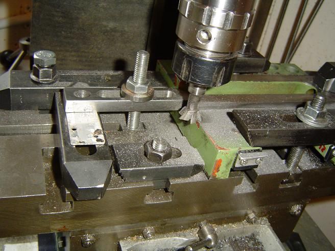
The job was done on my old Dore Westbury miller with a 60° dovetail cutter. Setting the saddle up wasn’t easy. The lathe is Chinese, so nothing is particularly parallel or square to anything else, and the only available datum faces were the two horizontal sliding surfaces on the top. I bought a couple of cheap Ebay feeler gauges to provide me with a variety of shims so I could get those sliding surfaces true. Here it is, with clamps everywhere I could fit one, including some  hemming it in, because the “shims” were shiny and slippery, and it would have been a disaster if the job shifted. 


Other problems encountered were:
1. Tramming the miller, which had to be done with the head at what would be working height (fairly low in this instance) in case its round column is not dead staight. In that case, altering its height after tramming would throw things out again. I adopted this rather nice technique http://rick.sparber.org/TM.pdf
2. The gib had conical dimples, no doubt made with a drill bit. The ends of the M4 adjusting screws weren't pointed or turned down in any way. As the dimples only roughly coincided with the screws, the gib had been twisting slightly as I tried to adjust it in the past. No wonder adjustment was always a compromise between no tight spots on the one hand and no free play on the other. To cure this, I flat-bottomed the dimples with a 4mm slot drill, faced the ends of the screws and turned the threads off their ends (happily, I have an old Perris baby lathe to use while the Chinese one was dismantled).
3. There are no saddle gibs bearing on the underside of the bed on my lathe. The side plates (those which normally carry the gib plate adjusting screws on Chinese saddles) were a close fit to the bed, so there was no discernible rock. In any case, unless I was turning something so large that the tool was no longer over the bed, or was using a back tool post, cutting forces would push the saddle down on to the bed, so the side plates would have nothing to do. But for some reason, after reassembly, the front plate was too tight on the bed, so I had to interpose  about a thou of kitchen foil shim between it and the saddle. The rear plate was too loose, so about 2 thou had to be removed by draw filing. The result was pretty good; no discernible rock, and the saddle can be lugged along the bed quite easily, without resorting to the apron handwheel.

All in all, I’m happy with the result. The dishing has been reduced to what for me are acceptable limits, the carriage is nicely fitted to the bed, and the cross-slide gib problem has been eliminated.

My thanks to all who took an interest, particularly Pete (Miner); I hope his recovery continues. Likewise, I trust that Norm (Fergus) is over his pneumonia.

Andy
Sale, Cheshire
I've cut the end off it twice, but it's still too short

Offline Miner

  • Full Member
  • ***
  • Posts: 176
  • Country: ca
Re: lathe cross slide 'dishing'
« Reply #48 on: September 24, 2012, 11:07:29 AM »
Hi Andy,
 :beer: You did a hell of a good job in my opinion. That's a huge improvment over what you started with.  You might want to recheck your lathe after it's done some work just to give you a general idea of the direction it's starting to wear in. (convex, concave) Due to the minor tool marks, you might see a quite high wear rate to begin with till the slides wear in a bit, and then the the actual wear rate will slow down to normal. It's the tool marks and direction they run why shapers are the preferred machine tool for non ground or hand scraped dovetails.

LOL, I'll bet you learned and now understand a lot more than you did before starting that job. There's a LOT more to proper machine tool alignment than most would think. But it's also not a job that should be rushed, and you have to be 100% certain of your test results and where the problem really is.

The last I heard Norm is doing much better, but it might be a couple of weeks before he checks back here. I'm doing........ok. Too many pills for breakfast though. :(

Pete

Offline andyf

  • In Memoriam
  • Hero Member
  • *****
  • Posts: 1795
  • Country: gb
    • The Warco WM180 Lathe - Modifications
Re: lathe cross slide 'dishing'
« Reply #49 on: September 24, 2012, 12:47:28 PM »
.... LOL, I'll bet you learned and now understand a lot more than you did before starting that job. There's a LOT more to proper machine tool alignment than most would think. But it's also not a job that should be rushed, and you have to be 100% certain of your test results and where the problem really is.

The last I heard Norm is doing much better, but it might be a couple of weeks before he checks back here. I'm doing........ok. Too many pills for breakfast though. :(

Pete

Damn right I didn't rush it, Pete, though I wasn't exactly putting in 8-hour days and did take 10 days off in France at the beginning of this month. I'm just a hamfisted amateur tinkerer, not a machinist. "Measure twice, cut once" - I must have checked about 8 times before each cut.

One question: the operation involved shaving a bit off each side of the saddle dovetail, so there's now about 1/12" daylight behind the gib strip. Does this matter, or should I be thinking about a new, thicker gib? To may way of thinking, the only time it might really matter is when taking cuts away from the headstck, when the pressure will be taken by three out of the four gib screws, which are only M4 and will be in clear air for over 1/12", including the end which passes into the modified dimples.

Andy
« Last Edit: September 25, 2012, 05:44:39 AM by andyf »
Sale, Cheshire
I've cut the end off it twice, but it's still too short

Offline Miner

  • Full Member
  • ***
  • Posts: 176
  • Country: ca
Re: lathe cross slide 'dishing'
« Reply #50 on: September 24, 2012, 01:16:10 PM »
Hi Andy,
Others may disagree, but if it were me? I'd make a new gib. Sooner or later any slack thruout the whole system will rear it's ugly head with chatter at the tool tip. I've been more than suprised a few times by thinking one thing, yet the tool itself doesn't cooperate with logic.

Do you have the George Thomas book The Model Engineers Workshop Manual? While it's about Myford lathes, he shows why the gib strip should be pinned in place to prevent even very minor movements of the gib in the direction the slide is moving, yet it still allows adjustment. If you don't have the book, just PM me your email adress and I'll scan the correct pages for you. There's some real good views about why the standard vee shaped points on the gib adjustment screws don't work as they should.

Pete

Offline andyf

  • In Memoriam
  • Hero Member
  • *****
  • Posts: 1795
  • Country: gb
    • The Warco WM180 Lathe - Modifications
Re: lathe cross slide 'dishing'
« Reply #51 on: September 24, 2012, 02:36:26 PM »
Thanks, Pete. PM sent.

I ran into a gib strip snag a while back, when replacing the solid nut on my little Perris's leadscrew with a half nut, running in a dovetail with a gib.  Couldn't get it to work smoothly until I realised that the adjustment screws through threaded holes in the frame were pushing the gib down the slope of the dovetail until they fouled the half nut. Easily fixed, but a lesson learned.

Pins would help prevent that happening, too.

I must shop around for some gauge plate, not that I would want to harden it, but for the sake of its ground surface.

Regards,
Andy
Sale, Cheshire
I've cut the end off it twice, but it's still too short

Offline Jonny

  • Hero Member
  • *****
  • Posts: 780
Re: lathe cross slide 'dishing'
« Reply #52 on: September 25, 2012, 10:10:21 AM »
Will be ok Andy, the screws will take that clearance up, dead easy to set up.
Just make sure the dimpling is deep enough in gibs.
Whilst at it i would drill and tap another hole to act as a lock.

A new gib needed if it was a tapered one.

Offline andyf

  • In Memoriam
  • Hero Member
  • *****
  • Posts: 1795
  • Country: gb
    • The Warco WM180 Lathe - Modifications
Re: lathe cross slide 'dishing'
« Reply #53 on: September 25, 2012, 12:00:45 PM »
Tapered goibs? On a cheap Chinese lathe??  :lol:

I redid the dimples with a slot drill, as mentioned earlier, so they had flat bottoms and lined up properly with the screws. Being on a 60 deg slope, the top side of each dimple is deeper than the lower side, but I made sure thee was a bit of depth all round.

I'm currently awaiting GHT's thoughts on gibs from Pete,  but in the meantime it occurs to me that there's another way to fill the gap behind mine. Make up a thin strip, like a gib, JB Weld it to the female side of the dovetail, put pins through it and into the gib proper as recommended by Pete and GHT for location, and continue the existing tapped holes for the adjuster screws through it.

The lathe did come with a central gib screw, with no lock nut, to immobilise the slide when needed. Wish I could fit one with a little handle, to save hunting out the right Allen key, but there's no room.

Andy
Sale, Cheshire
I've cut the end off it twice, but it's still too short

Offline andyf

  • In Memoriam
  • Hero Member
  • *****
  • Posts: 1795
  • Country: gb
    • The Warco WM180 Lathe - Modifications
Re: lathe cross slide 'dishing'
« Reply #54 on: January 16, 2013, 07:53:09 AM »
Hi Andy,
Others may disagree, but if it were me? I'd make a new gib. Sooner or later any slack thruout the whole system will rear it's ugly head with chatter at the tool tip. I've been more than suprised a few times by thinking one thing, yet the tool itself doesn't cooperate with logic.

Do you have the George Thomas book The Model Engineers Workshop Manual? While it's about Myford lathes, he shows why the gib strip should be pinned in place to prevent even very minor movements of the gib in the direction the slide is moving, yet it still allows adjustment. If you don't have the book, just PM me your email adress and I'll scan the correct pages for you. There's some real good views about why the standard vee shaped points on the gib adjustment screws don't work as they should.

Pete

Pete, I took your advice and made a new gib, which almost fills up the enlarged gap left after I machined the dovetails to get them squarer to the spindle. As you say, these things don't always follow logic, and one end of the gib wanted to dip down so its underside fouled the slide base. A pin at that end fixed the problem, and for the sake of completeness I added one at the other end, too.

Thanks for the advice, and for recommending the GHT book. As you say, it's written around the Myford, but there's still a lot of useful stuff in it.

Andy
Sale, Cheshire
I've cut the end off it twice, but it's still too short