Author Topic: Another 6 x 26 Knee Mill CNC conversion  (Read 42219 times)

Offline 9fingers

  • Jr. Member
  • **
  • Posts: 75
  • Country: gb
    • Info on Induction motors (Heavily UK based!)
Another 6 x 26 Knee Mill CNC conversion
« on: July 14, 2012, 08:21:50 AM »
Hi All,

New kid on the Mad Modder block here. I've just discovered this site when trawling for info on CNC conversion.
I've had a Myford VMC mill from new for the last 20 years or so and have been thinking sporadically about conversion to CNC for about half that time. Usually after a tedious session of pecking out profiles from a long list of Excel generated coordinates. :lol:

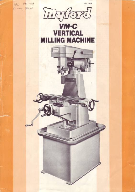
The VMC is quite similar to the generic 6 x 26 that appears worldwide with a range of badges with the exception that it does not have the fine quill feed that virtually all other 6 x 26 machines I've seen.
The original data sheet is here
and
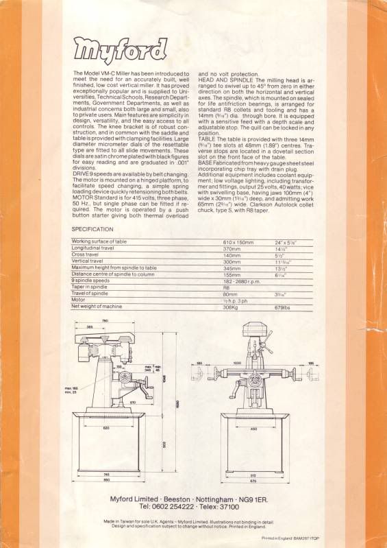


I've had a Heidenhain 2 axis DRO on it since new and a few years back swapped the DC motor I was using for get variable speed for a 3 phase 1hp induction motor and a Siemens Micromaster inverter that I run from 10Hz to 100Hz giving a range of 20% to 200% of the designed spindle speeds. The machine has had light hobby use from new and is still in pretty good condition.

A few years back I decided that in order to learn a little about stepper motors and drivers to change the homebrew X feed from a windscreen wiper motor and worm gearbox to a direct drive 3Nm stepper motor (that is about 400 of your strange 'merkin oz-inches  :lol:) Currently I still have the 4mm pitch feedscrew and the 3Nm motor is just about man enough to turn it.


My background is in electronics research and development so I tend to be an experimenter using suck it and see iterative methods rather than detailed paper design and build. Well that is my excuse anyway!
Throughout this conversion, I will have to make any parts needed using the target mill supplemented by Myford ML7RB for any turning and milling whilst the VMC is inoperable. This might turn into quite a challenge and as a last resort might be begging/borrowing time in other workshops :doh:

As I'm very much a novice in the area of CNC, I'm not proposing to make this write up a blow by blow account of how to do a CNC conversion. There are better threads here and elsewhere written by professional engineers for that sort of use.
I intend to post various sub topics here of my approach on the basis that it might just be of interest and maybe stimulate a discussion.

One such topic is my attempt to balance the load of the knee on the Z axis using a gas spring.

My first task was to estimate the weight of the knee. I wound it right up to the top of the slide, locked the Z axis and released the Z axis feed nut. Once SWMBO was out of the way, I used the bathroom scales to measure the force on the nut which was around 1000kN. Put another way - about the same as I weigh :bugeye:

The vertical travel is around 350mm and I found I could buy an adjustable gas spring with 1200kN force and 400mm travel here
http://www.sgs-engineering.com/gas-struts/range/nitride/adjustable/10mm-rod/gsv10-400

These springs are filled with nitrogen and oil and must be fitted cylinder uppermost to keep the seals moist and the gas inside.
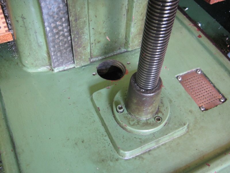
The spring is mounted centrally under the knee about 30mm away from the Z slideways.
I drill a clearance hole through the cast base and the sheet steel stand underneath with a starrett type hole saw. Pretty heavy going through 10mm thick cast iron and the sheet steel 100mm below. None too pretty result but it did the job!


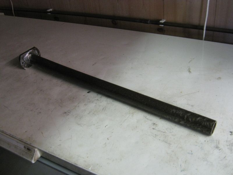
I used a length of 1" iron water pipe welded to a mild steel flange to house and support the piston end of the spring.


and
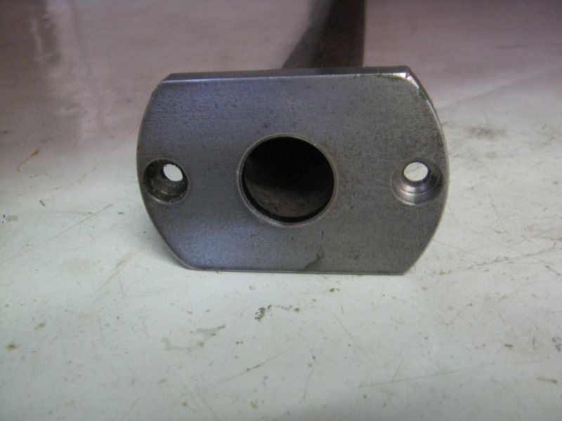


An M6 cross bolt (not shown) was fitted at the lower end of the pipe to support the piston end that was screwed into a short length of 22mm diameter steel bar. The cylinder is also 22mm diameter so the piston end is kept roughly central. Once is had 100Kg of knee pressing down, it won't be going anywhere!

To mark the underside of the knee casting I turned up a pointed steel plug to fit inside the tube flange and lowered the knee onto it - result one centre dot that I could then use a punch to enlarge.
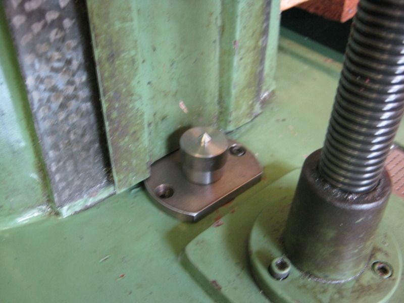


Drilling and tapping the casting  M8 was a bit awkward with a right angle drive cordless drill and a small tap wrench with removable tommy bar.

Here is a the ball end fitted ready to receive the gas spring cylinder. There is a choice of end fittings available included in the price of the gas spring.
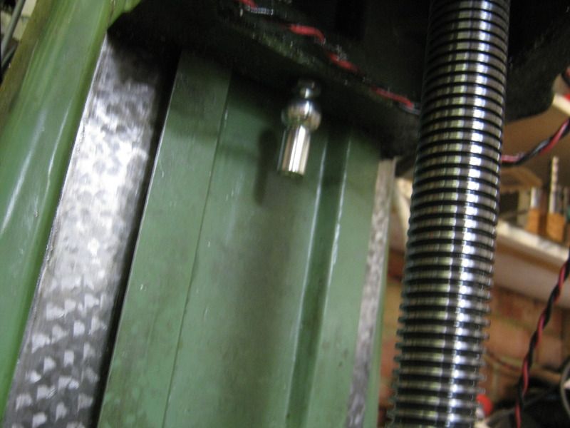


Getting the spring into position is a bit tricky. uncompressed it is 850mm long before any end fittings are added.

I need to jack the knee up another 80mm above its usual maximum position. So by locking the knee, undoing the nut and inserting spacers underneath, I could use the Z screw to achieve this.
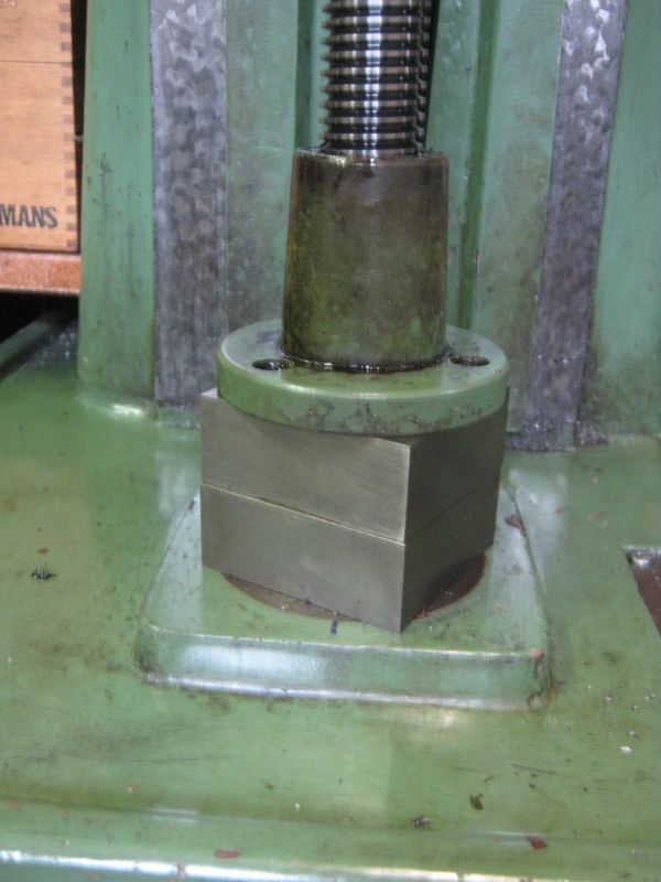


With the cylinder fitted to the knee casting I could then remove the spacers and refit the nut securing screws.

Winding the knee up and down felt most peculiar. Remember we have 1200kN force upwards and 1000kN imposed by the knee. So it take MORE effort to lower the knee than raise it :D

I then used a spring balance and the feedscrew handle to measure the difference in torque need to raise and lower the table whilst gently letting some gas out of the spring one fart at a time remembering that there is no way back if I let too much out!

I've used these springs before and it is actually fairly easy - a sub one second burst makes a small but measurable difference.

I've now got it balanced quite nicely now and it takes about a 2kg pull at 200mm radius - about 4Nm to move the table in either direction.

My next step is to attach a stepper in place of the handle and see how well or otherwise that works. A 12Nm motor  and matching driver are on order from Zapp and some timing pulleys from http://www.beltingonline.com/ - a new supplier to me but the prices seem good. Lets hope the service matches!

More in a few days with luck.
I hope this is of interest - comments welcome
Bob


Offline John Stevenson

  • In Memoriam
  • Hero Member
  • *****
  • Posts: 1643
  • Nottingham, England.
Re: Another 6 x 26 Knee Mill CNC conversion
« Reply #1 on: July 14, 2012, 09:38:16 AM »
Bob,
I think you need to rethink the 12 Nm motors, they are far to big and powerful for this machine.
problem with large motors is the detent torque needed to overcome the rest position. To overcome this take time and power with the result that the motors are slow and in short moves of which a lot of CNC moves are they spend most of their time accelerating and not running at the speed they should.

As an idea that big Beaver CNC of mine which i know you have seen uses 7Nm motors direct driving onto 0.2" pitch ballscrews which is close to 5mm pitch and has no problems.

John S.
John Stevenson

Offline 9fingers

  • Jr. Member
  • **
  • Posts: 75
  • Country: gb
    • Info on Induction motors (Heavily UK based!)
Re: Another 6 x 26 Knee Mill CNC conversion
« Reply #2 on: July 14, 2012, 09:50:28 AM »
Thanks for your input John. I guess I was afraid of not having enough power to lift the knee especially as I'm hoping not to have to use a ballscrew for the Z axis if I can help it.
I did consider the comments about 12Nm speed in Rob's 6 x 26 thread and will be using much more agile motors for X & Y.
I'm still of two (or three minds!) whether to put a stepper on the quill for majority of the Z operations.

Any thoughts on  CNCing the quill  would be of great interest especially interlinking it with a powered knee. Can Mach 3 cope with two Z drivers?

TIA

Bob

Offline loply

  • Sr. Member
  • ****
  • Posts: 260
Re: Another 6 x 26 Knee Mill CNC conversion
« Reply #3 on: July 14, 2012, 10:20:12 AM »
Hi Bob,

Far from an expert but I have done quite a bit of reading as I'm slowly gathering bits for CNC'ing my mill and lathe.

I note that individuals are often concerned about not having enough power for their Z axis, yet I can't ever find a reference to anybody ever having a problem with this.

Cheers,
Rich

Offline Brass_Machine

  • Administrator
  • Hero Member
  • *****
  • Posts: 5504
  • Country: us
Re: Another 6 x 26 Knee Mill CNC conversion
« Reply #4 on: July 14, 2012, 11:25:54 AM »
Hiya Bob  :wave:

Welcome to the collective :borg:

Very glad to see you are sharing your build with us. I will be following!

Eric
Science is fun.

We're all mad here. I'm mad. You're mad.

Offline 9fingers

  • Jr. Member
  • **
  • Posts: 75
  • Country: gb
    • Info on Induction motors (Heavily UK based!)
Re: Another 6 x 26 Knee Mill CNC conversion
« Reply #5 on: July 14, 2012, 12:15:18 PM »
Hiya Bob  :wave:

Welcome to the collective :borg:

Very glad to see you are sharing your build with us. I will be following!

Eric

Thanks for the welcome Eric.

I dunno about followers - I think I need some leaders too  :lol:

Bob

Offline John Stevenson

  • In Memoriam
  • Hero Member
  • *****
  • Posts: 1643
  • Nottingham, England.
Re: Another 6 x 26 Knee Mill CNC conversion
« Reply #6 on: July 14, 2012, 05:00:45 PM »
Did a search because I had read an article by Tony Jeffee when he converted his X3 and did some tests on the Z axis.

He was using the largest type 23 motor at the time sold by ARC. These are 2.2Nm motors and he was driving a 2mm pitch ball screw directly.

End of the day he finished up putting a set of bathroom scales on the bed and pushed down. He bailed out at 137Kg because he didn't want to break the scales.

When we were doing the X3 conversion kits we were using the same motors with 4mm pitch screws, direct drive on X ans Y and 2:1 reduction on the Z. No complaints and no problems.

Later WM series machines have had 5mm pitch screws and the 3Nm motors fitted again direct on X and Y, 2:1 reduction on Z. Again no problems.

In your case Bob with the gas strut on the knee Zapps 5504 or 6004 motors driving a 16 x 5 screw would be more than enough and faster than Robs setup.

[edit] The VM-B I am doing will have 16 x 5 screws, 3 Nm motors, direct on X and Y and 2:1 on the Z and run at 72 volts driving the larger ARC drivers. I do not see any problems with this setup.

John S.
John Stevenson

Offline doubleboost

  • Madmodder Committee
  • Hero Member
  • *****
  • Posts: 1619
  • Country: gb
  • Newcastle Upon Tyne
Re: Another 6 x 26 Knee Mill CNC conversion
« Reply #7 on: July 14, 2012, 05:47:27 PM »
Hi
Bob
I also have a 626 mill  :doh: :doh:
Although i have no intension of doing a cnc conversion , i will be copying your gas strut mod  :thumbup: :thumbup:
My mill has a 6 inch riser block so i will need a bit more stroke on the ram
I have been looking  at car tail gate  struts but your link has convinced me not to be such a "tight arse" and just buy one for the job
Good luck with your conversion (you have some good people on this forum ready to help )
John

Offline 9fingers

  • Jr. Member
  • **
  • Posts: 75
  • Country: gb
    • Info on Induction motors (Heavily UK based!)
Re: Another 6 x 26 Knee Mill CNC conversion
« Reply #8 on: July 15, 2012, 07:00:21 AM »
I thought I replied to this last night but can't see it this morning? But I did have a few drinks.......

The riser block that I have does not add any Z travel but just increases the daylight under the quill nose so the same 400mm gas spring will still do the job. In fact a 350mm would possibly do but it makes it all the more critical to align the knee travel to the spring travel.

Bob

Offline John Stevenson

  • In Memoriam
  • Hero Member
  • *****
  • Posts: 1643
  • Nottingham, England.
Re: Another 6 x 26 Knee Mill CNC conversion
« Reply #9 on: July 15, 2012, 07:06:45 AM »
Bob,
This is true about aligning, any sideways force on the rod will wear the seal and they soon start to leak.
Don't ask  :wave:
Contrary to popular engineering practice if you can get as much bag and flop in the mounting and allow it to self centralise the better it is.
John Stevenson

Offline 9fingers

  • Jr. Member
  • **
  • Posts: 75
  • Country: gb
    • Info on Induction motors (Heavily UK based!)
Re: Another 6 x 26 Knee Mill CNC conversion
« Reply #10 on: July 15, 2012, 07:15:47 AM »
Very true John.

My comment use of the word alignment was probably a bad choice. I just meant that using a 400mm strut meant that it was less critical to get the vertical position of the strut right so that it did run out of steam when the knee was at max height or indeed limit the knee travel at the lowest point.
Sort of being lazy on the measurements. In any case the supplier I linked to does not sell 350mm struts and one who does
http://www.strutsdirect.co.uk/components/variable-force-gas-struts-sd03.php does not offer the in line ball & socket end fittings.

Bob

Offline doubleboost

  • Madmodder Committee
  • Hero Member
  • *****
  • Posts: 1619
  • Country: gb
  • Newcastle Upon Tyne
Re: Another 6 x 26 Knee Mill CNC conversion
« Reply #11 on: July 15, 2012, 08:35:23 AM »
Hi
Bob
Just had a bit measure up 400 will be ideal (360 )travell before the screw comes out of the nut
John

Offline 9fingers

  • Jr. Member
  • **
  • Posts: 75
  • Country: gb
    • Info on Induction motors (Heavily UK based!)
Re: Another 6 x 26 Knee Mill CNC conversion
« Reply #12 on: July 15, 2012, 10:44:27 AM »
I've just been sent this link by Ron Ginger about his conversion. It is for a 8 x 28 mill but it's pretty similar to the 6 x 26.

http://plsntcov.8m.com/JetMill/Jet.html

Bob

Offline 9fingers

  • Jr. Member
  • **
  • Posts: 75
  • Country: gb
    • Info on Induction motors (Heavily UK based!)
Re: Another 6 x 26 Knee Mill CNC conversion
« Reply #13 on: July 19, 2012, 08:54:42 AM »
I've been starting to think about ballscrews for the X and Y slide whilst waiting for parts to arrive for the Z axis.

There is plenty of room in the area of the Y screw but the X axis is going to be tight. I'm trying to minimise the machining needed once I have the mill in pieces. Even though a mate has offered me use of his mill to make parts, I don't want to impose on him too much.

I've decided on 20mm ballscrews and Zapp have a couple of ball nuts with a 34mm body diameter which will just fit in with 1mm clearance. However, the flange is 57mm diameter with two flats 40mm across and I wanted to see how they would fit before splashing the cash.

I made a replica of the flange from 1/2" aluminium.


The cut out in one side was in the hope that I could slot it over the 1" diameter feedscrew but no such luck  :doh:
So the end of the table had to be taken off which in the end gave a much better view of the problem.

There is very little room arounf the existing nut.


I clamped the flange to the table end.


and marked the table to show where it interferes


I considered that machining that much off the table would weaken the dovetail too much and so marked the flange where it would interfere.


Removing that much from the ball nut flange will destroy one mounting hole but I reckon the remaining 3 should be enough especially if I add some sort of clamp around the body of the nut as well.

I think I've done enough to satisfy myself that the X ballscrews can be made to fit even though it seems a bit brutal to attack a brand new nut in this way.

The next job, whilst I have the table end/bearing carrier off is to counter bore the inside face to admit the ballnut flange and to open out the bore to take a second bearing. Straight forward faceplate work on the lathe. This will allow room for two opposed A/C bearings (7204-2RS) to support the ballscrew

Current bearing is a 6303z which has the same OD as the a/c ones (47mm) but a 17mm bore to suit the old feedscrew. The new ones are 20mm bore which will be ideal for my ballscrew end adaptors.

That's all for now folks.

Bob


Rob.Wilson

  • Guest
Re: Another 6 x 26 Knee Mill CNC conversion
« Reply #14 on: July 19, 2012, 10:30:16 AM »
Sounds like you have a plan Bob  :thumbup:

It is a bit tight getting these parts into a mill that was not designed to take ballscrews  :palm:


Rob

Offline 9fingers

  • Jr. Member
  • **
  • Posts: 75
  • Country: gb
    • Info on Induction motors (Heavily UK based!)
Re: Another 6 x 26 Knee Mill CNC conversion
« Reply #15 on: July 19, 2012, 12:52:19 PM »
Yes Rob, things are starting to come together - at least to an outline plan.

I have to confess to everyone about an error in my first post. I got my N & kN mixed up :doh: :doh:

The knee weighs about 100kg thus exerting 1000N

The gas spring is rated at 1200N

Sadly I still weigh more than 100kg - the only bit I got right. :lol:

Bob

Offline 9fingers

  • Jr. Member
  • **
  • Posts: 75
  • Country: gb
    • Info on Induction motors (Heavily UK based!)
Re: Another 6 x 26 Knee Mill CNC conversion
« Reply #16 on: July 19, 2012, 02:04:31 PM »
I got a bit more done this afternoon.

I bored the bearing housing to take the second bearing.


A spare 6204ZZ fitted for the photo together with the original 6303Z just visible


Dummy flange fitted to illustrate the counterbore. The X axis traverse stop will continue to be the breaing housing hitting the saddle as per original design and not risk damaging the ball nut.


Everything has arrived now for the Z drive. 1/2" plate, motor, timing pulleys & belt so that will be the next job.

Bob

Rob.Wilson

  • Guest
Re: Another 6 x 26 Knee Mill CNC conversion
« Reply #17 on: July 19, 2012, 03:48:43 PM »
Hi Bob  dose this mean its now a three CNC horse race  , Yourself  ,Mr JS and I  ,I will lay odds i will come last  :palm:


Looking forward to seeing what you make from your 1/2" plate  :dremel:


Rob

Offline dsquire

  • In Memoriam
  • Hero Member
  • *****
  • Posts: 2275
  • Country: ca
  • Kitchener, Ontario, Canada
Re: Another 6 x 26 Knee Mill CNC conversion
« Reply #18 on: July 19, 2012, 03:54:45 PM »
Hi Bob  dose this mean its now a three CNC horse race  , Yourself  ,Mr JS and I  ,I will lay odds i will come last  :palm:


Looking forward to seeing what you make from your 1/2" plate  :dremel:


Rob

Rob

That may be but I am willing to bet yours is the shiniest. Especially with that patented trade secret camera process you use.  :lol: :lol: :lol:

Cheers

Don
Good, better, best.
Never let it rest,
'til your good is better,
and your better best

Offline John Stevenson

  • In Memoriam
  • Hero Member
  • *****
  • Posts: 1643
  • Nottingham, England.
Re: Another 6 x 26 Knee Mill CNC conversion
« Reply #19 on: July 19, 2012, 06:19:53 PM »
Hi Bob  dose this mean its now a three CNC horse race  , Yourself  ,Mr JS and I  ,I will lay odds i will come last  :palm:


Rob

No way my VM-B has took back seat, done a little drag engraver the other week as it was needed, the shop clear out after getting rid of the big TOS is taking longer than I thought.

Problem is damn customers, no matter how much you swear at them, take the pi$$ and be as obnoxious as possible the bastards still keep coming back.

Keep getting phone calls about the new laser and when can they deliver it but so far nowhere finished to put it, mind you once it does hit the deck that's another diversion.
John Stevenson

Offline DMIOM

  • Hero Member
  • *****
  • Posts: 676
  • Country: gb
  • Isle of Man
Re: Another 6 x 26 Knee Mill CNC conversion
« Reply #20 on: July 20, 2012, 03:34:57 AM »
..........Problem is damn customers, no matter how much you swear at them, take the pi$$ and be as obnoxious as possible the bastards still keep coming back........

No, you've missed the point - if you're still providing top-notch services (even if they're not chrome-plated) then they'll keep coming back!   maybe its even the Gordon Ramsay effect?   :lol:

Quote
...........Keep getting phone calls about the new laser and when can they deliver it but so far nowhere finished to put it....

Tell you what, I'd be very glad to help - I'll look after it & get it run-in for you, rent-free  :thumbup:

Dave

Offline 9fingers

  • Jr. Member
  • **
  • Posts: 75
  • Country: gb
    • Info on Induction motors (Heavily UK based!)
Re: Another 6 x 26 Knee Mill CNC conversion
« Reply #21 on: July 23, 2012, 11:49:02 AM »
I got some more work in on the Z axis drive over the weekend.

I machined up a plate to hold the motor onto the Z axis shaft and in the process managed to make it 6mm too short  :bang:
So I can't tension the belt properly  :doh:


Viewed from the rear to show the motor.


A shorter belt should have been delivered this morning but Parcel Farce sent it to the Gatwick Airport depot instead of my local one which is Southampton Airport  :doh: Hopefully it will turn up tomorrow.

However I could not wait to give it a quick try out. So I raided my electronics junk box and cobbled together a 60v supply and connected up the driver in test mode which turns the motor slowly.
So by no means a realistic test but the table moves under power! :D


Click picture to view short video clip.

The manual handle was left attached to show the rotation. Obviously this would normally not be fitted!

Bob

Offline Ronkh

  • Jr. Member
  • **
  • Posts: 35
  • Country: england
Re: Another 6 x 26 Knee Mill CNC conversion
« Reply #22 on: July 23, 2012, 01:29:45 PM »
Nice going Bob but for God's sake disengage otherwise watch yer nut's!  :lol:
Just me!

Rob.Wilson

  • Guest
Re: Another 6 x 26 Knee Mill CNC conversion
« Reply #23 on: July 23, 2012, 03:52:30 PM »
 :thumbup:  nice going Bob  :clap: :clap: :clap:


Rob

Offline 9fingers

  • Jr. Member
  • **
  • Posts: 75
  • Country: gb
    • Info on Induction motors (Heavily UK based!)
Re: Another 6 x 26 Knee Mill CNC conversion
« Reply #24 on: July 23, 2012, 04:00:18 PM »
Thanks Guys

 :thumbup:

Trying to decipher the Chinglish manual for the driver now..... :bang:

Bob