Author Topic: Rod's Lathe stand project  (Read 17715 times)

Offline RodW

  • Full Member
  • ***
  • Posts: 120
  • Country: au
    • Vehicle Modifications Network
Rod's Lathe stand project
« on: June 10, 2013, 11:41:52 PM »
Well it all started when I bought a coolant pump cheap


And after I fitted up the plumbing to the splash guard


while I was moving my lathe  back where it belonged I did this


Which needed some ingenuity to get back on its feet


And then someone on the forum here shared this picture of a lathe stand with removable casters


So it got me thinking as I had an identical drawer unit to the ones used.

As it turned out, my lathe was a fair bit shorter and my shed is a fair bit smaller so this was going to be about 8" too long for me. Also, I needed clearance for the coolant return drain. So I bought a 3 drawer toolbox and promptly hacked the lid off it and everything looked like it was going to fit well


Then I went and got some steel


and finetuned my 6x4' bandsaw as it was not cutting square


I consulted my carefully crafted CAD drawing


and spent a day hacking bits down to size. I am using 65x35mm rails for the top and 35mm x 35mm SHS for legs and lower braces.


Does not look much like a day's work does it?


RodW
Brisbane, Australia

Offline RodW

  • Full Member
  • ***
  • Posts: 120
  • Country: au
    • Vehicle Modifications Network
Re: Rod's Lathe stand project
« Reply #1 on: June 10, 2013, 11:42:34 PM »

I drilled some holes in the legs to mount the casters while I could get them under my mill


And drilled and tapped some 10mm plate for adjustable legs


Of course, I ran out of welding gas on a weekend after 3 spot welds so the next weekend, I decided to try laying out a jig for a change. This worked out well and kept it square.


Then it was time to tack on the legs


 I only spot welded on one leg the wrong way....

Then used a spacer to mount the bottom rail


A couple of them needed clamping to get back square


Starting to look like a bench


The lathe drip tray hangs down a bit below the mounting points so the cross members need to be set a bit higher than the frame. I drilled the holes before I started on the mill to keep them square and initially was going to use the dimensions in the manual but I decided I better check them. Very pleased I did, the holes were actually 7mm further apart than the plan said.


Made these holes 13mm for 10mm bolts to add a bit of wiggle room.


I tried things for fit while it was still mostly spot welded.  We should see some detail pics later but to keep the stand compact, I used a 5mmx50mm flat bar in the centre supports as an inverted T to hold the tool boxes and the outside edges are sitting on 25x25x3mm angle iron.


Looks like this will work out OK. but I need to add a hanger so I can cut away the back half of the angle iron cross member so I can slide the coolant tank in from the end as the pump fouls the angle iron.


The drawer units had some threaded holes to hold handles in place so I decided to incorporate them to hold the drawer unit in and found that the transfer screws I had purchased recently made this very easy to mark out hole positions.


To hold the small toolbox into position, I added a couple of nutserts into the toolbox so I could bolt it on without stuffing about with nuts. (Note to self: if you decide to clamp a crocked part straight before welding out,  do it befoore you add the nutserts!)


RodW
Brisbane, Australia

Offline RodW

  • Full Member
  • ***
  • Posts: 120
  • Country: au
    • Vehicle Modifications Network
Re: Rod's Lathe stand project
« Reply #2 on: June 10, 2013, 11:44:26 PM »
Overnight, I had a chance to reflect on things and progress so far. I decided that because I had a second identical drawer unit in the shed, I would add it as well!


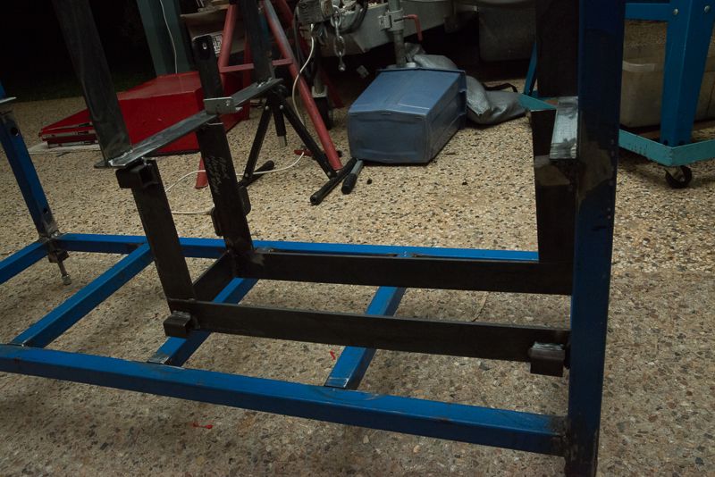
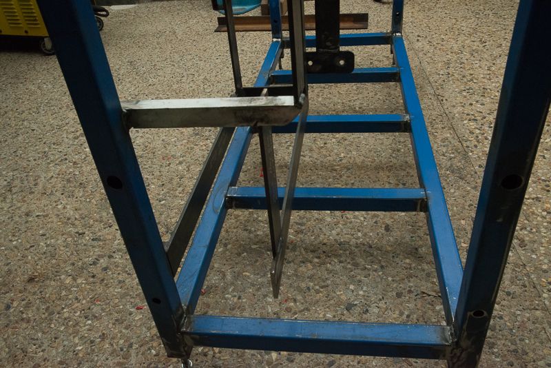
You can see I also added a couple of extra braces to the bottom shelf.

For this pic, I jammed the lid of the toolbox in the back above the coolant tank and it looks like I could add a small shelf for odd stuff but it will have a hose running through it. You can see I have fixed the cross member that was in the road.


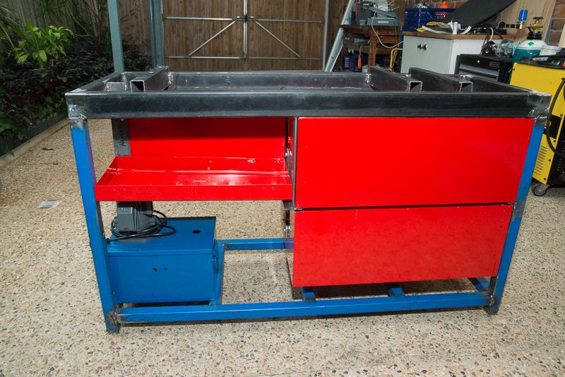
I don't know if I will put this in here yet, but certainly food for thought!

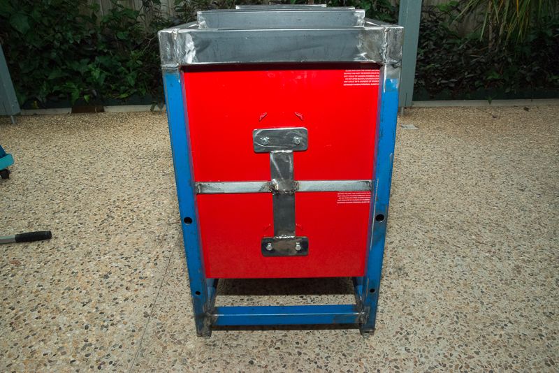
The bottom drawer unit is just hanging down from the handle mounts.


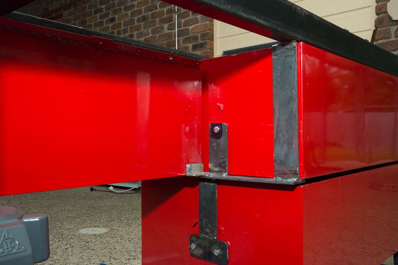
and a few more shots to show you the detail


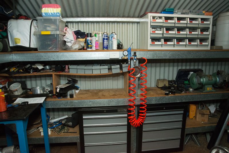
So pulling the second drawer unit out of my shelf has opened up a bit of a gap in the shed


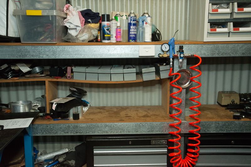
Hmm, I gotta fix that  wonky shelf. I've got some material here I bought for the job.

So here is the plan for a future project. The lathe destroyed a drawer in the cabinet on the way down and I bought a replacement to make good the damage.


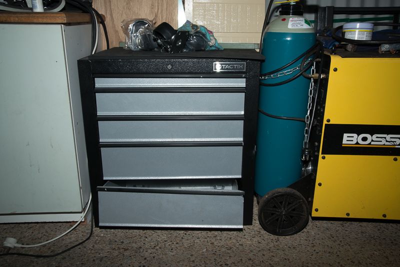
I worked out that I should be able to cut the bottom drawer away and the remaining 4 drawers will slide into the available space. This will look nice and neat as I have 2 of these drawer units in the shed already.


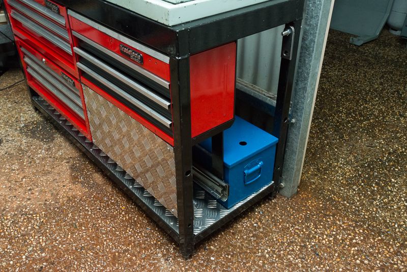
I decided  that there was some spare space beside the coolant tank and I had a set of surplus 550mm long x 100kg drawer runners here that were itching to be used on something and they were the perfect length so I set about making up a frame to hold them from 5mm x 50mm flat bar.


** Post 4

So the frame was pretty much done and ready for paint aside from a few finishing bits. It is pretty cold here and not good paint drying weather so I decided to paint it Friday evening and fiddle with other stuff for a day while the paint dried.


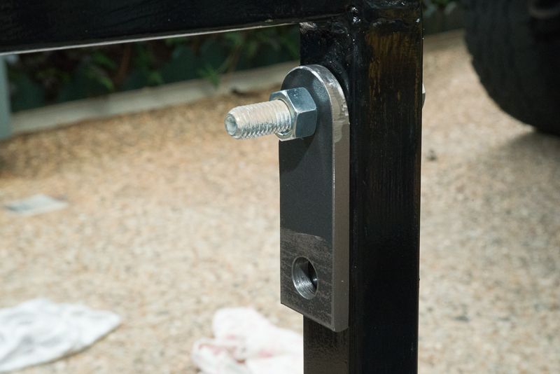
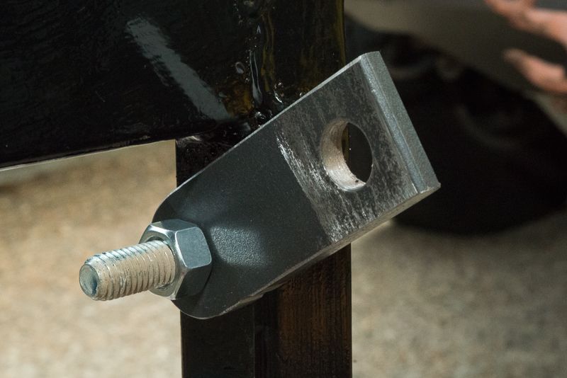
Chris down the road suggested I add some lifting points to the frame and I thought this was a really good idea but his idea of adding some eye bolts was not going to work, so I came up with this idea and added two foldaway lifting tabs secured with M12 bolts at diagonally opposite corners.


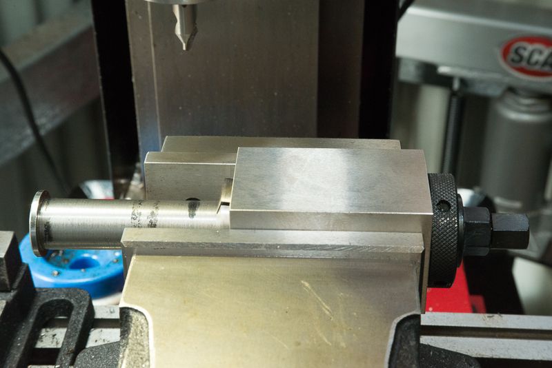
The other thing I needed to do was to turn up some mounting pins for the external legs


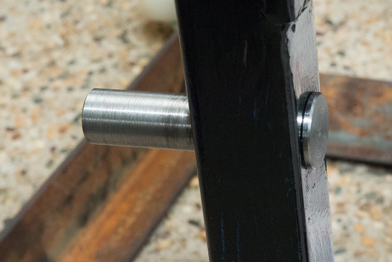
Because of the tight clearances, the heads had to be less than 3mm thick. I started with 25mm steel and turned it down to 19mm. By using the cariage stop I made and a piece of rod held in the tailstock, I ended up keeping the dimensions identical which I was pleased with. I just have to work out where to drill the holes for the leg pivot points.

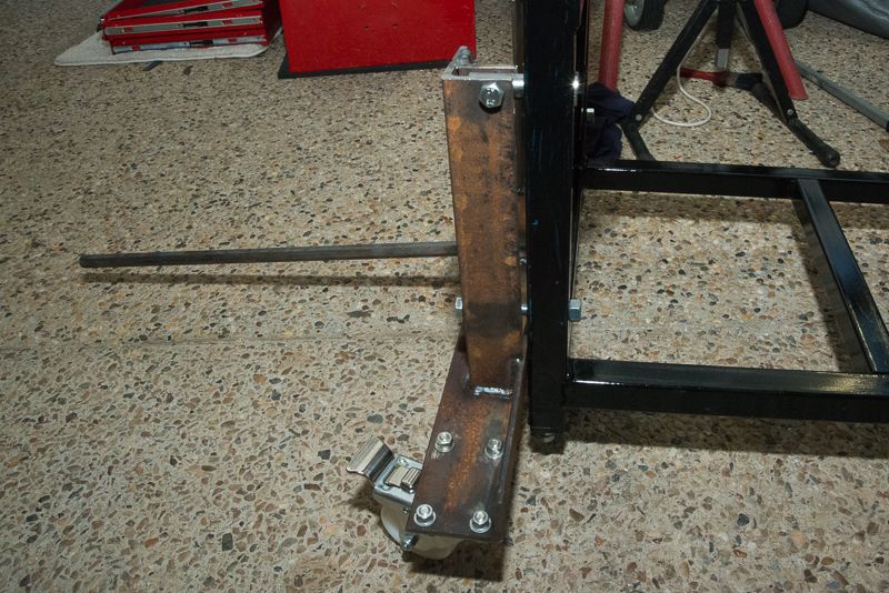
It took a while to drill the mounting holes for the casters and I had decided to buy some fancy 125 kg casters instead of using some unknown capacity wheels that came on the grey drawer units that I replced with home made adjustable feet. Of course the brake lever on the new casters hit the stand legs so I had to make sure the wheel mounts were set slightly off centre to get clearance. I am using 50mm x 75mm x 6mm angle iron for this.

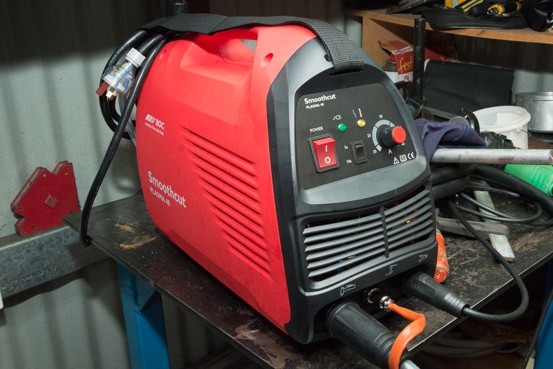
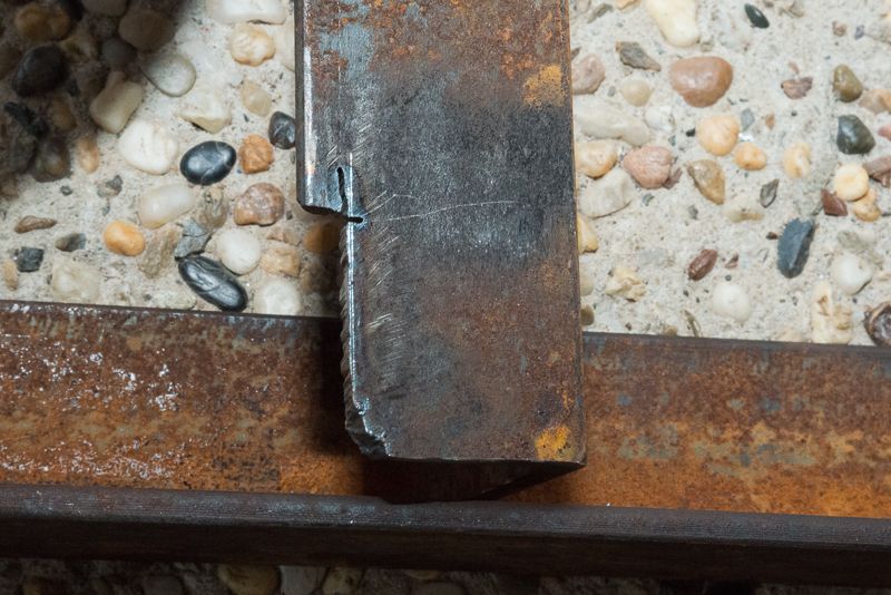
The upright needed notching which was a good chance for me to play with my new plasma cutter


Nothing like a live job for the very first cut and you can see I got a bit carried away. I have never used one of these suckers before but I like it a lot!


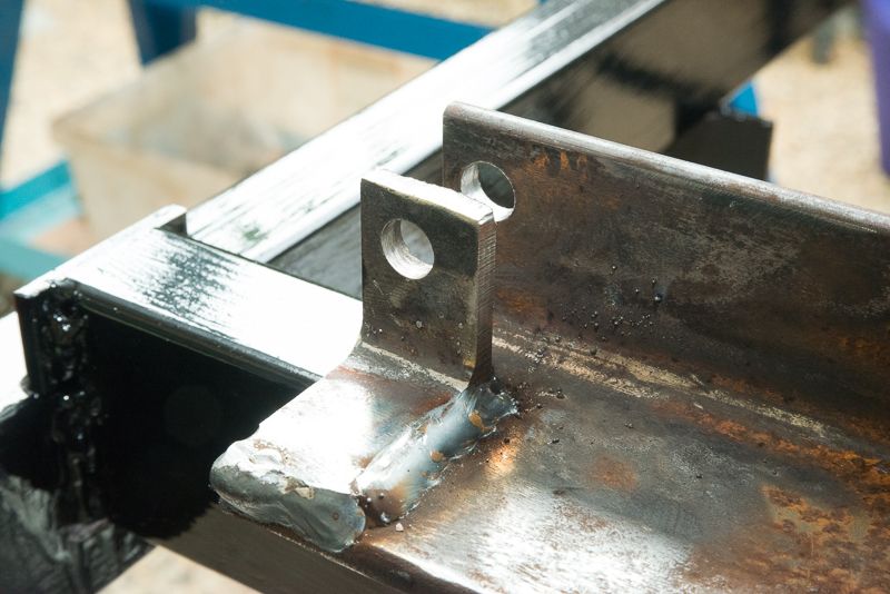
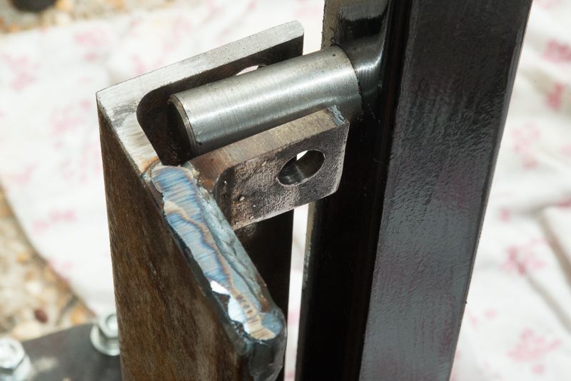
So after working out the height required for the leg uprights, I drilled an 11 mm hole in the top of each one and  used the plasma to trim up some short pieces of angle iron to form a tab. I drilled the hole through the tab back on the mill so I could use the existing hole as a guide.


Looks like this is going to work out OK, I just need to drill the cross holes in the pins


So back to the mill and I grabbed my collet blaock and the collet stop I had bought from Little Machine Shop. I used an edge finder to find the edge of the pin and moved over to centre the part under the drill. I still don't have a spotting drill, so I used a centre drill to start the hole.


and followed through with an 11mm drill.


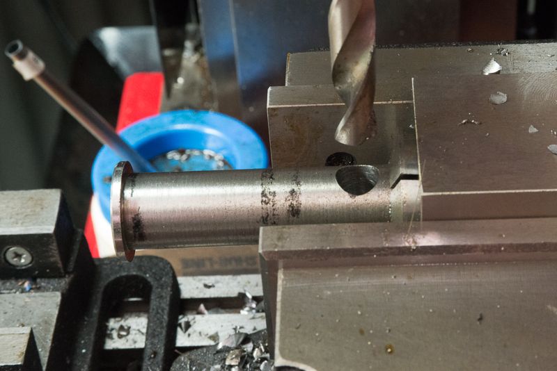
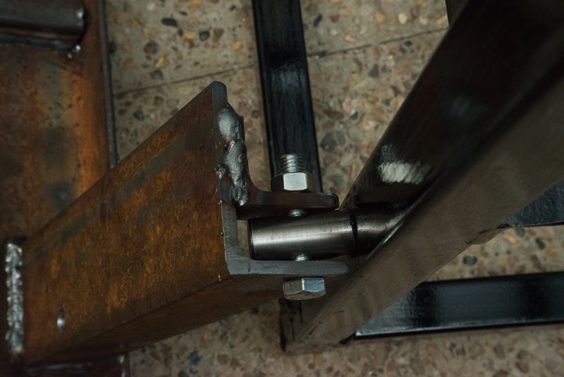
This workflow worked really well as I drilled the 4 pins with one setup and everything was identical. So now the hinge for the top of the legs is complete


I decided I would not bother with using a hand winch to pull the stand up on its wheels as a lever would work just as well. So I welded on a bit of 25mm SHS to hold one.


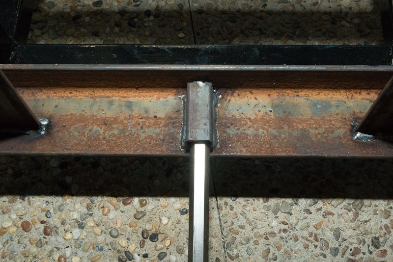
The lever for now is some 16mm Hex bar I had here. It really needs to be replaced with something that is a tighter fit in the SHS but I thought a 25mm dia lever turned down to fit the SHS would be a bit of overkill!

So the idea is to bolt the wheel assembly on, insert the lever into the leg.
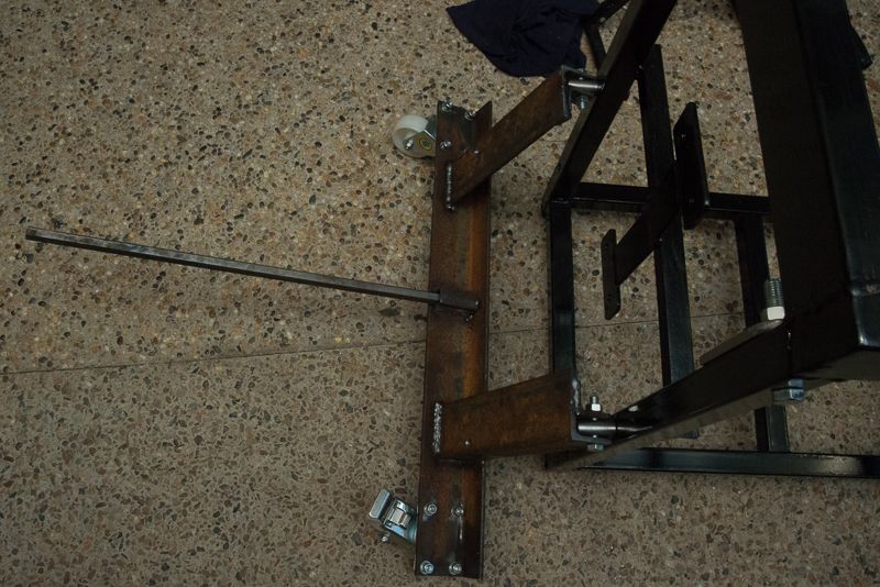


And stomp on it!


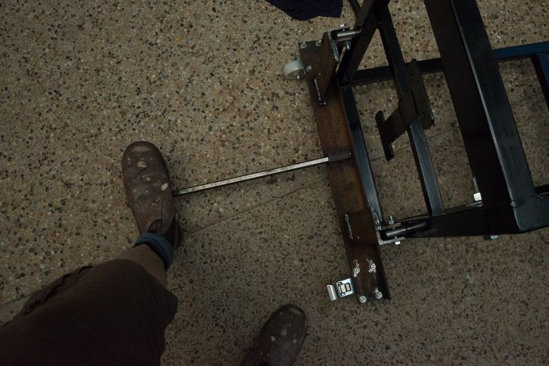
and secure the leg with a 12 bolt each side down the bottom.


It will be pretty cool if this actually works once the lathe goes on!

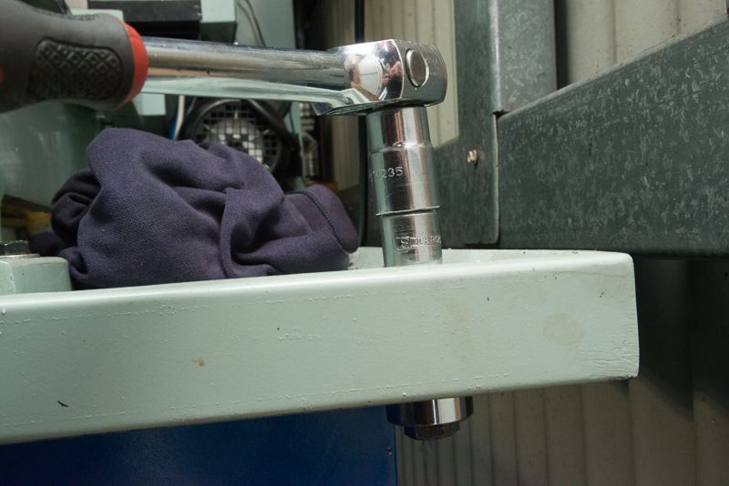
So now time to look at making provision for a coolant drain. Chris had also suggested to press a dimple in the drip tray using two sockets. I had to do this in situ so thought I  would see if I could just use a bolt through a 12mm hole to achieve the same result.


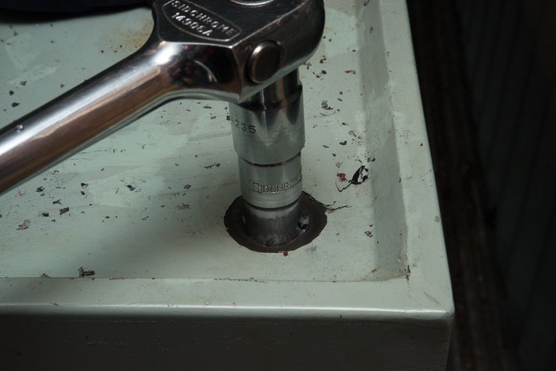
This actually worked really well.


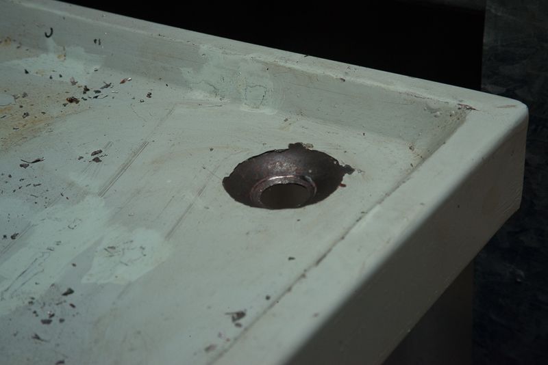
I had seen a steel 3/4" hose joiner with a barb on each end and I thought if I was to part it in the centre, it would make a good tail.


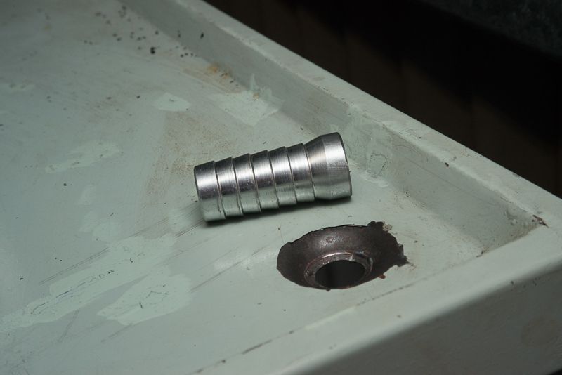
Chris said he welded them on. I was a bit worried about this as it was going to have to be an overhead weld in situ as I did not expect the drip tray to come away from the lathe after I Sikaflexed it on the first time. Of course as I expected I blew a hole through which was still OK after a bit of a repair but at the last minute I tried to patch a pin hole and totally stuffed it! So you are just going to have to wait until I tidy it up to see a photo.

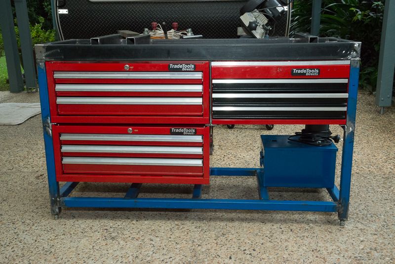
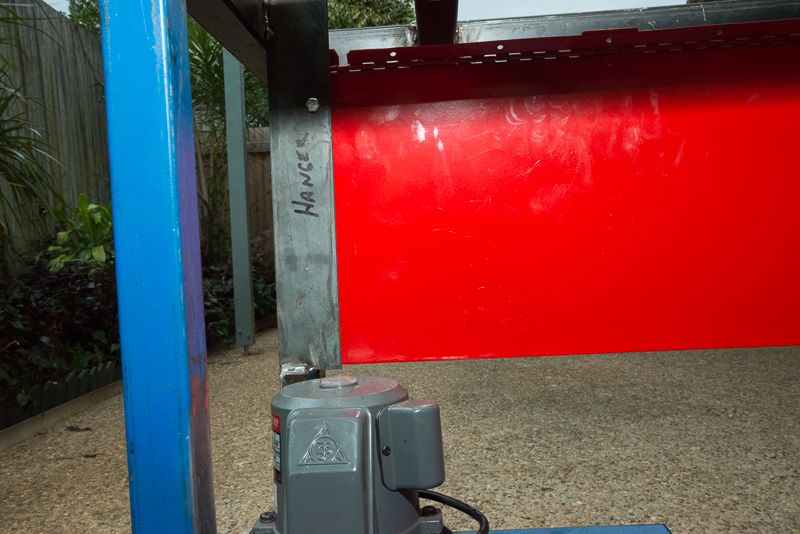
Well, ready to comission this thing. You can see I used some checker palte to make it go faster. The front cover plate in front of the drawer unit is held on with stainless domed screws but the bottom shelf is pop riveted on.


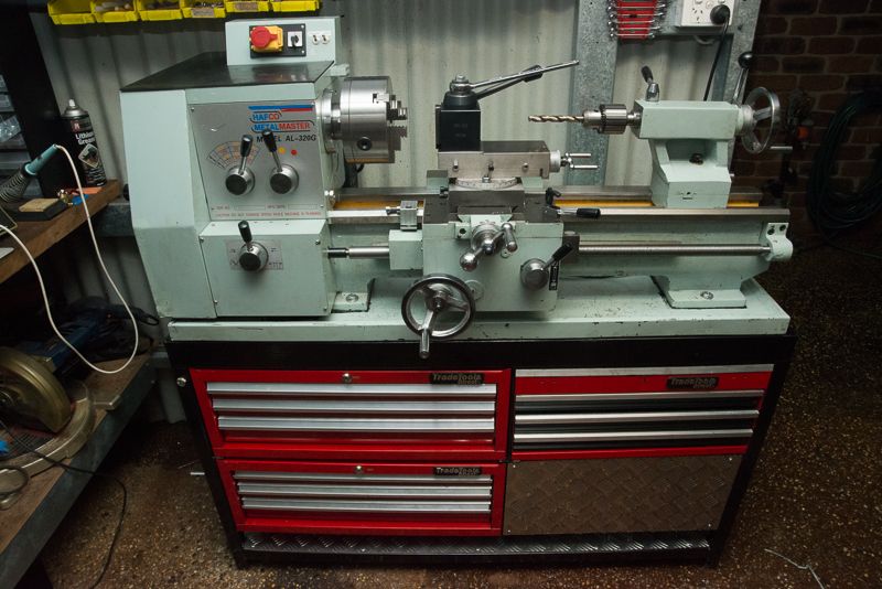
It looks good and I got the mounting hole dimensions spot on.


Still have to sort out the drawer unit yet!


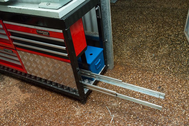
I bought a right angle drill head today so I can drill a couple of holes at the front to finish off mounting the drawer runners. I knew I would have problems with this when I built it but as I did not really know how it was all going to mount up at the time, I decided to just press on as it was hard enough getting everything into position and tacked up on my own.

Anyway, I will update this as I finish it off over the next week or so. I would like to make the drawer out of the checkerplate but I can't bend it myself so I might just get somebody to make it for me yet.
RodW
Brisbane, Australia

Offline dsquire

  • In Memoriam
  • Hero Member
  • *****
  • Posts: 2275
  • Country: ca
  • Kitchener, Ontario, Canada
Re: Rod's Lathe stand project
« Reply #3 on: June 11, 2013, 12:30:34 AM »
Rod

Looks like you made a great job Rod. You have certainly turned the initial disaster on its ear. Thanks for shareing that with us.  :D :D

Cheers  :beer:

Don
Good, better, best.
Never let it rest,
'til your good is better,
and your better best

Offline Henning

  • Full Member
  • ***
  • Posts: 136
  • Country: no
  • All the kit and no clue!
Re: Rod's Lathe stand project
« Reply #4 on: June 11, 2013, 02:30:17 AM »
VERY nice work! Lots of ideas for when i will be building mine! Although i fear i will have to make lots and lots of it out of horrible brown stuff... 

 :nrocks:   :proj:
Henning

Just because i can't, doesn't mean i shouldn't?
Tool- lover, with a collection to show for it!

Rob.Wilson

  • Guest
Re: Rod's Lathe stand project
« Reply #5 on: June 11, 2013, 02:52:44 AM »
 :thumbup:  you have made a cracking job of the new stand Rod  :clap: :clap: :clap:


Rob

Offline RodW

  • Full Member
  • ***
  • Posts: 120
  • Country: au
    • Vehicle Modifications Network
Re: Rod's Lathe stand project
« Reply #6 on: June 11, 2013, 07:39:01 AM »
Thanks for the encouragement guys. I am still not finished yet but I made a bit more progress today

I went shopping today and grabbed a couple of tools.


Tradetools had a sale on so I grabbed a 90 degree drill attachment and some hex drive drills so I can eventually finalise the mounting of the drawer slide. I was also going to get a set of tooling for my dremel but then saw the die grinder for only $33  which I decided would be a better option to sort out my Cr@ppy welds. And this is what I ended  up with.


I know it is not pretty but but will be hidden under the splash guard mount and a coat of paint will do wonders! It is not obvious in the photo but there is still quite a dish around the drain.  I went to a kitchen shop and they did not have anything like a conical strainer I liked so I grabbed a round strainer and shaped it round my finger and a metal rod for a while and poked it into the drain. The drain is well way from where I work so I don't think much cr@p will end up this end.

I enlarged the hole in the top of the coolant tank with a 32m step drill and the hose fits in nicely now.


I also finished off the plumbing for the outlets which are attached to the rear splash guard.


The mounting block came with the coolant kit but I had to mill 10mm off it and enlarge the hole as I ditched the pipe that came with it that it was designed to clamp to and now it clamps to the larger diameter pipe fitting instead. The slimming operations were required to allow the pipe fittings to screw together.

In case you are wondering about the two taps, the coolant will enter from the rear on the left had side and flow via T piece hidden inside the mounting block and up to the top tap and barb for for the lathe coolant. The bottom tap on the right exits to another barb at the rear to eventually run coolant over to the mill on the other side of the door.

So I think the next step is to paint the drip tray tomorrow night and the final plumbing can be done for the inaugural switching on later in the week! It is frustrating that I have had the coolant system for a month and it is still not operational!

Sort of part of this project is a bit of wiring I did while I was putting the lathe back on its feet. The top electrical box needed straightening so while I was at it, I added some power points wired into the lathe.

Shown here exiting the lathe control box


and the outlets themselves. The colour coding was deliberate and come from some cheap extension leads I cut down.


I decided the DRO power did not need to be switched but I added switches for coolant and the light to the front of the box.


 I am really looking forward to baptising the system with coolant by flicking the switch soon!
RodW
Brisbane, Australia

Offline black85vette

  • Jr. Member
  • **
  • Posts: 60
Re: Rod's Lathe stand project
« Reply #7 on: June 11, 2013, 09:00:44 AM »
Impressive amount of planning and fabricating.   Nice that you have a custom result that is just what you want.  Good job. :clap:

Offline Meldonmech

  • Hero Member
  • *****
  • Posts: 933
Re: Rod's Lathe stand project
« Reply #8 on: June 11, 2013, 01:44:16 PM »
Hi Rod
                Great job, and using all that valuable space. Nice to have all your tooling handy in the drawers.

                                                 Well Done  Cheers David

Offline RodW

  • Full Member
  • ***
  • Posts: 120
  • Country: au
    • Vehicle Modifications Network
Re: Rod's Lathe stand project
« Reply #9 on: June 13, 2013, 07:42:25 AM »
Hi Rod
                Great job, and using all that valuable space. Nice to have all your tooling handy in the drawers.

                                                 Well Done  Cheers David

Hi Rod
                Great job, and using all that valuable space. Nice to have all your tooling handy in the drawers.

                                                 Well Done  Cheers David

Thanks guys.

Well tonight was the moment I have been waiting a month to get to. Coolant is Live!


I was surprised how clear the coolant fluid is when it is mixed up.

The drain came up alright. It is always amazing how much difference a coat of paint makes


The 3/4" drain easily copes with draining the fluid back to the tank and the slight fall towards the back corner the drain is situated in works a treat so not much pools anywhere.


The drain is protected somewhat as it is located under the back splash guard  mount.


Sorry, it was a bit late tonight so I have tried any cuts but I will over the weekend. There is a bit of splash when it is running but I found putting a small low plastic container under the bed where the coolant was hitting the deck helped to control this.

After I took these photos, I decided to put the chuck guard back on, I got a feeling I might need it! It is looking a bit worse for wear after the fall but it is still serviceable.
RodW
Brisbane, Australia

Offline krv3000

  • Hero Member
  • *****
  • Posts: 2183
  • Country: gb
Re: Rod's Lathe stand project
« Reply #10 on: June 13, 2013, 05:45:40 PM »
grand work well dun

Offline micktoon

  • Hero Member
  • *****
  • Posts: 797
  • Country: gb
Re: Rod's Lathe stand project
« Reply #11 on: June 13, 2013, 06:12:28 PM »
Hi Rod , Nice job , glad nothing got too badly damaged when the l;athe toppled over , you must have been lucky there ! Thanks for good post plenty pictures and you have made good use of the space with the drawers etc.
  Cheers Mick.

Offline BlueRock

  • Jr. Member
  • **
  • Posts: 6
Re: Rod's Lathe stand project
« Reply #12 on: June 13, 2013, 06:16:41 PM »
Sweeet looking job Rod, well done!

Offline Stilldrillin

  • Global Moderator
  • Hero Member
  • *****
  • Posts: 4972
  • Country: gb
  • Staveley, Derbyshire. England.
Re: Rod's Lathe stand project
« Reply #13 on: June 14, 2013, 05:22:29 PM »
That has worked out very well Rod!  :thumbup:

Well done, and well shown......  :clap: :clap:

David D
David.

Still drilling holes... Sometimes, in the right place!

Still modifying bits of metal... Occasionally, making an improvement!

Offline RodW

  • Full Member
  • ***
  • Posts: 120
  • Country: au
    • Vehicle Modifications Network
Re: Rod's Lathe stand project
« Reply #14 on: June 15, 2013, 03:55:58 AM »
grand work well dun

That has worked out very well Rod!  :thumbup:

Well done, and well shown......  :clap: :clap:

David D

Hi Rod
                Great job, and using all that valuable space. Nice to have all your tooling handy in the drawers.

                                                 Well Done  Cheers David

Hi Rod
                Great job, and using all that valuable space. Nice to have all your tooling handy in the drawers.

                                                 Well Done  Cheers David

Thanks for the encouragement guys. I spent a bit of time today grinding off the rust and painting the leg assemblies so I can say it is totally done. Sorry, I did not take any photos. but you have seen it all already, just that it looks nicer now! I think that just leaves the drawer on the end to finish off.

Yes, I am very pleased with the detail in the photos I have taken. I think my camera setup is worth more than my mill and lathe put together as I have a Nikon D800 and because the pics are 36 megapixels, there is heaps of scope to crop them down to focus on the subject.

Hi Rod , Nice job , glad nothing got too badly damaged when the l;athe toppled over , you must have been lucky there !
  Cheers Mick.

Mick, thanks. The only thing that really got damaged was one of my new gray drawer units. I decided to buy another one at $275 as they were a clearance line and was the only ones that I had seen that fitted under my benches. The bottom drawer was a writeoff so I decided to take my new Plasma cutter to it and cut out the cancer!

I thought I would start at the back so when I stuffed it up no one would notice. :bugeye:


So here we are setup for the first cut. I decided to screw down a guide to get a straight cut as my hands are not very steady... I also hit the ends with the angle grinder so I had a bit of shiny metal to start cutting on. My plasma is  a scratch start and the manual says to drag the tip on the work you are cutting.


And it worked awesomely!


Before long, after cutting away some braces on the inside, I had shortened it nicely. I also had to cut the MDF shelf on the bench away to get enough clearance between the two shelves.


What a lot of fun plasma cutters are!  :thumbup:

And you can see I finally straightened the wonky shelf. I replaced the MDF with a 19mm x 235mm pine shelf so it should be strong enough. If it sags, I will put a steel or ally shelf in its place...


Now it seems the only problem I have is that I don't have enough tools to fill the 20 drawers i now have at my disposal!   :beer:

I think the only thing left shed wise now is to make a mounting plate to screw on the wall to hold my QCTP holders.. oh and trim a bit more of the base of the drawers that I cut away and put it on wheels so I can roll it under my bottom shelf for more storage....   :nrocks:
RodW
Brisbane, Australia

Offline jim4472

  • Jr. Member
  • **
  • Posts: 6
  • Country: gb
  • Tadley, Hampshire, UK.
Re: Rod's Lathe stand project
« Reply #15 on: June 16, 2013, 04:52:25 PM »
What a brilliantly thought out and executed recovery  :clap:

only problem I see is filling those drawers.

excellent project.

well done Rod

Jim
Location:- Tadley, Hampshire, UK
Skype:- gb7iha

Offline Davo J

  • Sr. Member
  • ****
  • Posts: 475
  • Country: au
Re: Rod's Lathe stand project
« Reply #16 on: June 17, 2013, 12:23:24 AM »
Great work Rod, that whole set up has come out nice.

Dave

Offline RodW

  • Full Member
  • ***
  • Posts: 120
  • Country: au
    • Vehicle Modifications Network
Re: Rod's Lathe stand project
« Reply #17 on: June 17, 2013, 03:36:12 AM »
only problem I see is filling those drawers.


Thanks Jim. Yes finding more tools to fill all the extra drawer is a bit of a problem. I mentioned the drawer filling concept to my wife and it did not receive a warm response!

Great work Rod, that whole set up has come out nice.

Dave

Thanks Dave, I had to do a short lathe job this evening and once I remembered where everything was, it was good to have everything at my finger tips . I will say that I opened about 5 drawers before I remembered where the new home is for my hammer to change the mill drawbar....  :bang:
RodW
Brisbane, Australia