Author Topic: Side Valve i.c. engine from Bar stock  (Read 112260 times)

Offline Brian Rupnow

  • Full Member
  • ***
  • Posts: 228
Side Valve i.c. engine from Bar stock
« on: August 01, 2014, 04:32:02 PM »
My current quest is to design and build a simple one cylinder, four cycle engine from barstock--(no castings). I am in the very early stages of design for this engine, and as it comes a bit clearer to me I will post my progress. The biggest stumbling block on an engine of this type is the complex machining required on the cylinder/valve body. I hope to simplify this by making the cylinder and valve body in two separate easy to machine pieces. This is where I am, so far.---Brian
Still thinking---

Offline dickda1

  • Full Member
  • ***
  • Posts: 161
Re: Side Valve i.c. engine from Bar stock
« Reply #1 on: August 01, 2014, 07:02:56 PM »
Yes,  please keep us updated
sunny (mostly) San Francisco, land of looney people, sane politics and occasional earthquakes.
Skype: VladTheChemist

Offline Brian Rupnow

  • Full Member
  • ***
  • Posts: 228
Re: Side Valve i.c. engine from Bar stock
« Reply #2 on: August 01, 2014, 08:52:21 PM »
My mind and computer take me to strange places----

Offline Brian Rupnow

  • Full Member
  • ***
  • Posts: 228
Re: Side Valve i.c. engine from Bar stock
« Reply #3 on: August 02, 2014, 11:20:18 AM »
Not there yet, but slowly getting all the parts in---

Offline Brian Rupnow

  • Full Member
  • ***
  • Posts: 228
Re: Side Valve i.c. engine from Bar stock
« Reply #4 on: August 02, 2014, 04:13:56 PM »
I think this could work---The cyan blue backplate would be 3/8" steel with 3 steel stub shafts welded into it. It would attach with 6 bolts and two locating dowels (not shown) to the dark green spacer bar, which is itself bolted and dowelled to the aluminum crankcase. The gears and cams might be machined from bronze or cast iron, something with enough lubricity that they can rotate on the fixed shafts without galling. The con rod has sealed needle bearings in both ends, the dark blue half of the split crankshaft has two sealed ball bearings supporting the end where the flywheel goes. The "follower half" of the split crankshaft would run in bronze bushings. The blue bridge which spans across the top of the aluminum crankcase is the tappet guide, and could be aluminum.


Offline Brian Rupnow

  • Full Member
  • ***
  • Posts: 228
Re: Side Valve i.c. engine from Bar stock
« Reply #5 on: August 02, 2014, 06:11:58 PM »
Okay!!---I am happy with everything here, and know it will work. The only "grey" area is attaching the valve body to the cylinder and the cylinder to the crankcase.--I haven't spent any time thinking about the flywheel, and I am pretty certain that like the Jaguar/Canadian Cub engine that I just built, this one will need a built in fan for cooling. The exhaust will be simply a screw-in straight pipe, and the carburetor will either be a copy of the Jaguar carb or my version of the George Britnell carb clone.

Offline tom osselton

  • Hero Member
  • *****
  • Posts: 1255
  • Country: ca
Re: Side Valve i.c. engine from Bar stock
« Reply #6 on: August 02, 2014, 07:56:35 PM »
I would extend the tappet guide to mate with the stub/gear plate to stop any flex or vibration bolting it as a solid piece.

Offline vtsteam

  • Global Moderator
  • Hero Member
  • *****
  • Posts: 6463
  • Country: us
  • Republic of Vermont
Re: Side Valve i.c. engine from Bar stock
« Reply #7 on: August 02, 2014, 09:36:58 PM »
Cool! I like the way you've done the cam gears.  :thumbup:
I love it when a Plan B comes together!
Steve
https://www.youtube.com/watch?v=4sDubB0-REg

Offline Stilldrillin

  • Global Moderator
  • Hero Member
  • *****
  • Posts: 4972
  • Country: gb
  • Staveley, Derbyshire. England.
Re: Side Valve i.c. engine from Bar stock
« Reply #8 on: August 03, 2014, 03:55:56 AM »
Looking good Brian!  :thumbup:

Watching, quietly.....  :beer:

David D
David.

Still drilling holes... Sometimes, in the right place!

Still modifying bits of metal... Occasionally, making an improvement!

Offline awemawson

  • Global Moderator
  • Hero Member
  • *****
  • Posts: 8966
  • Country: gb
  • East Sussex, UK
Re: Side Valve i.c. engine from Bar stock
« Reply #9 on: August 03, 2014, 05:08:41 AM »
Looking good Brian  :bow:

What CAD package are you using?  ('cos I like it  :wave:)
Andrew Mawson
East Sussex

Offline Brian Rupnow

  • Full Member
  • ***
  • Posts: 228
Re: Side Valve i.c. engine from Bar stock
« Reply #10 on: August 03, 2014, 09:41:26 AM »
Looking good Brian  :bow:

What CAD package are you using?  ('cos I like it  :wave:)
Solidworks

Offline Brian Rupnow

  • Full Member
  • ***
  • Posts: 228
Re: Side Valve i.c. engine from Bar stock
« Reply #11 on: August 03, 2014, 01:40:45 PM »
I gave up on the idea of having a steel backplate with welded in stubshafts. Last night I lay in bed thinking, and I had originally intended to solder the cams onto the face of the gears. This is always a somewhat "iffy" proposition, and as I have said all along, I want to be able to adjust the cam timing independent of the gear teeth. I decided I would be able to do that if I added a hub and set screws to one side of the gears and silver soldered the cams to the 3/8" shaft, while leaving the gears free to rotate into whatever position I wanted them to be in relation to the cam position, then lock them to the shaft with the set screws in the gear hub. This means of course, that the shafts must now be able to rotate. So---I changed the steel plate to an aluminum plate, with two 1" long oilite bronze bushings pressed into the thick part of the plate. The blue circles you see are the heads on the ends of the two cam shafts. They need shallow heads on them to keep then from trying to pull out of the bushings as they revolve. The other end of the camshafts which support the gears and the cams is still cantilevered, but it's only a 7/8" cantilever from the edge of the aluminum plate out to the centerline of the cams, so I don't anticipate any bending. The jockey gear is made from bronze and rotates on a 3/8" steel shoulder bolt which screws into the side of the crank case.

Offline Brian Rupnow

  • Full Member
  • ***
  • Posts: 228
Re: Side Valve i.c. engine from Bar stock
« Reply #12 on: August 03, 2014, 02:20:06 PM »
We have to get a set of my favourite Chrysler product ignition points mounted somewhere, and since we are in the design phase, I might as well mount them on an adjustable plate so I can adjust the ignition timing while the engine is running. That is easy enough to do by extending the end of the outer crankshaft bushing and bumping up the extended diameter to 5/8". I can then clamp the ignition points mounting plate onto the head of the bushing.

Offline tom osselton

  • Hero Member
  • *****
  • Posts: 1255
  • Country: ca
Re: Side Valve i.c. engine from Bar stock
« Reply #13 on: August 03, 2014, 03:34:58 PM »
Shouldn't the points be on the cam you don't want them firing every revolution?

Offline awemawson

  • Global Moderator
  • Hero Member
  • *****
  • Posts: 8966
  • Country: gb
  • East Sussex, UK
Re: Side Valve i.c. engine from Bar stock
« Reply #14 on: August 03, 2014, 03:58:20 PM »
A timing chain and three sprockets would greatly simplify the gear set up
Andrew Mawson
East Sussex

Offline Brian Rupnow

  • Full Member
  • ***
  • Posts: 228
Re: Side Valve i.c. engine from Bar stock
« Reply #15 on: August 03, 2014, 06:09:43 PM »
Shouldn't the points be on the cam you don't want them firing every revolution?
No, I quite often put the points on the crankshaft. You do get a "waste spark" but it does no harm, because the piston is at top dead center on the exhaust stroke, just getting ready to go down on intake stroke when this spark occurs. There is nothing in the cylinder to ignite.

Offline Brian Rupnow

  • Full Member
  • ***
  • Posts: 228
Re: Side Valve i.c. engine from Bar stock
« Reply #16 on: August 03, 2014, 06:13:49 PM »
A timing chain and three sprockets would greatly simplify the gear set up

Andrew--We are talking some pretty miniature stuff here. The pitch diameter on the crankshaft gear is only 5/8"  (16mm). It's difficult to get roller chain that small, and then arrange for a take up system for when the chain stretches. I have seen no other engines in this size range with a roller chain drive.----Brian

Offline awemawson

  • Global Moderator
  • Hero Member
  • *****
  • Posts: 8966
  • Country: gb
  • East Sussex, UK
Re: Side Valve i.c. engine from Bar stock
« Reply #17 on: August 04, 2014, 02:34:27 AM »
Perhaps a toothed timing belt then. They come pretty small
Andrew Mawson
East Sussex

Offline Brian Rupnow

  • Full Member
  • ***
  • Posts: 228
Re: Side Valve i.c. engine from Bar stock
« Reply #18 on: August 04, 2014, 12:42:00 PM »
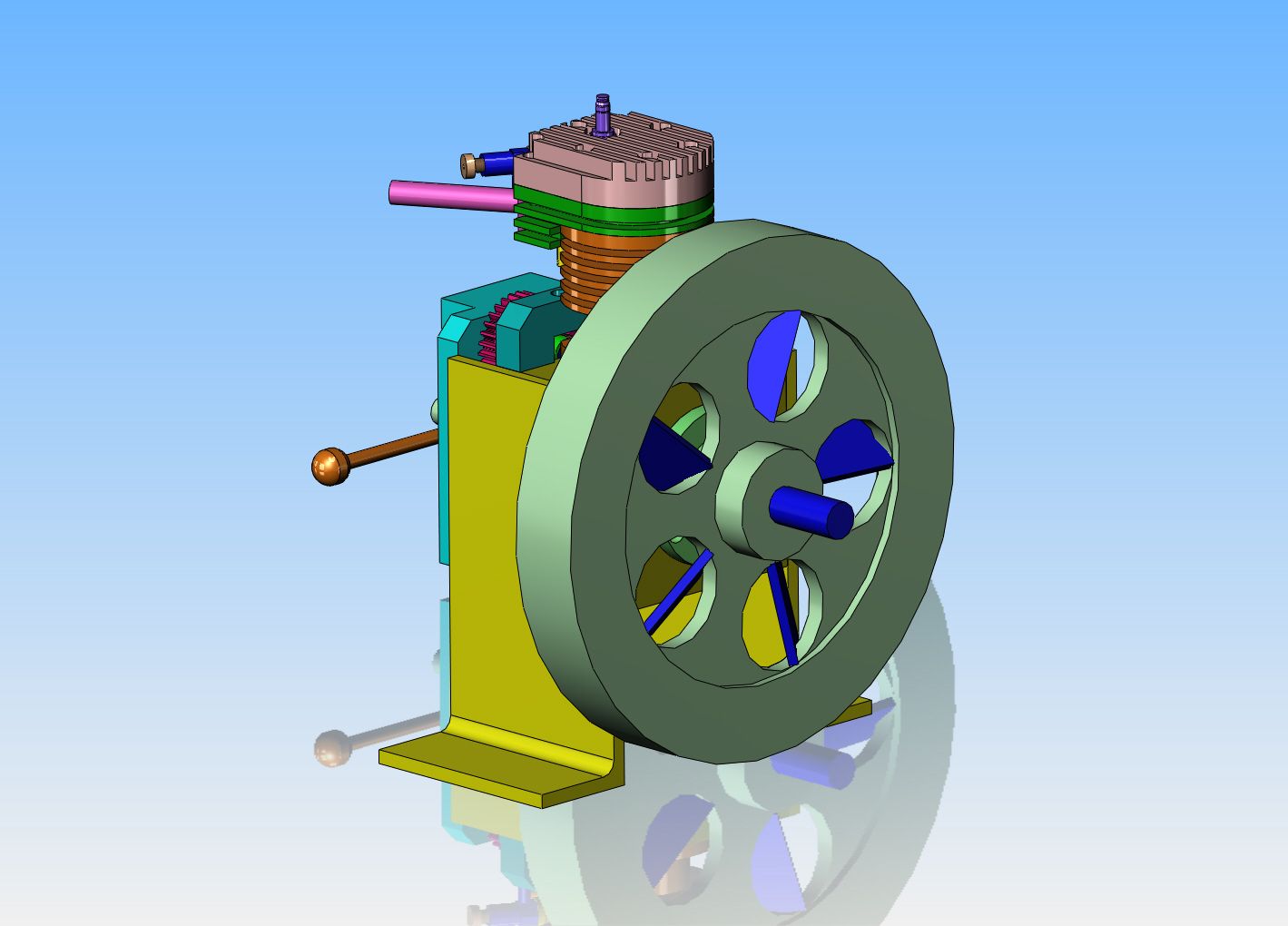
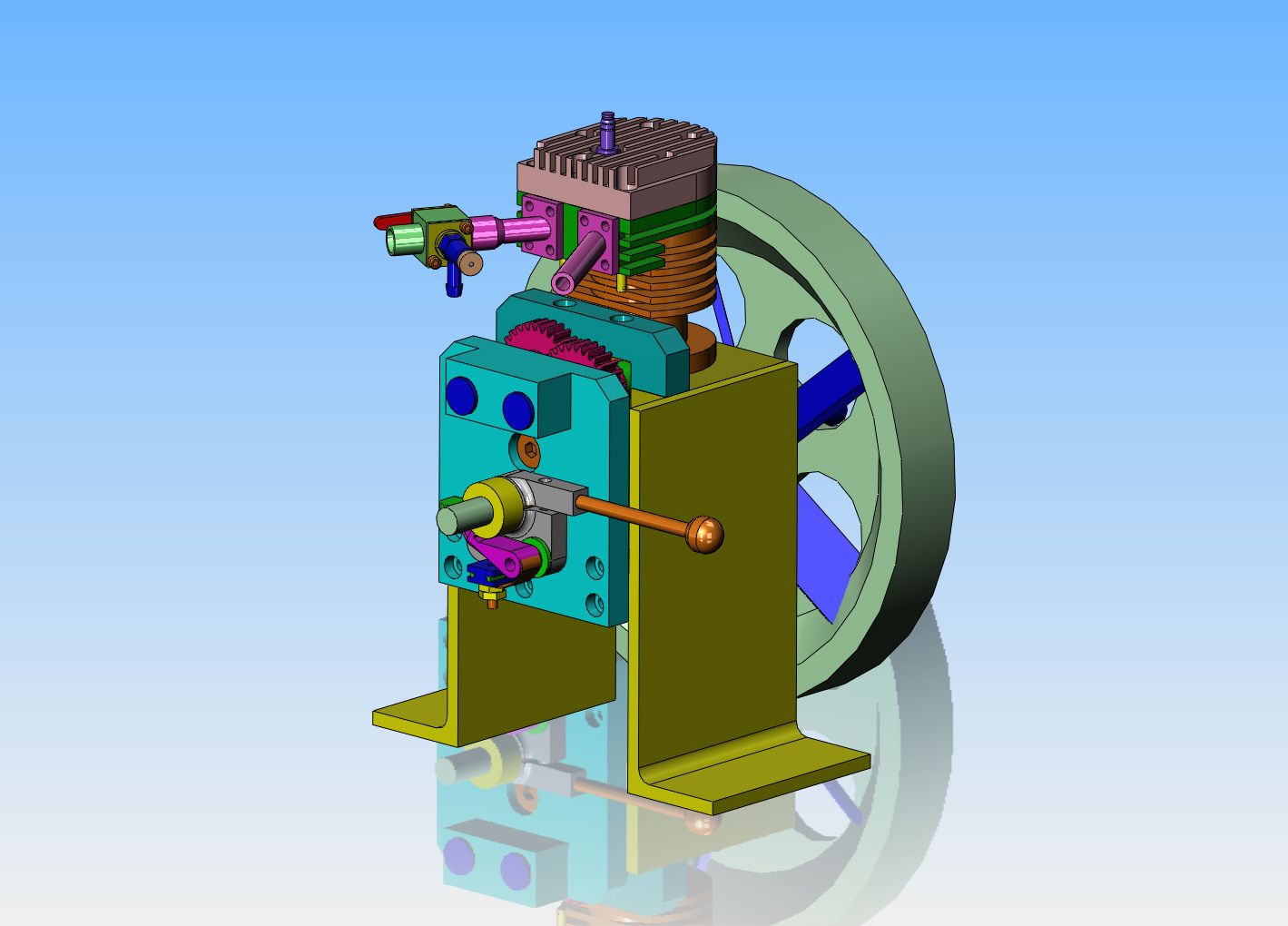
This is the point at which things begin to get a bit----goofy? The engine needs a flywheel. Past experience has proven to me beyond a doubt that the larger diameter a flywheel is, the better the engine will run and idle. Throttle response won't be as quick, because that's a lot of mass to move, but if fast throttle response isn't vitally important, then a large diameter flywheel is the way to go.
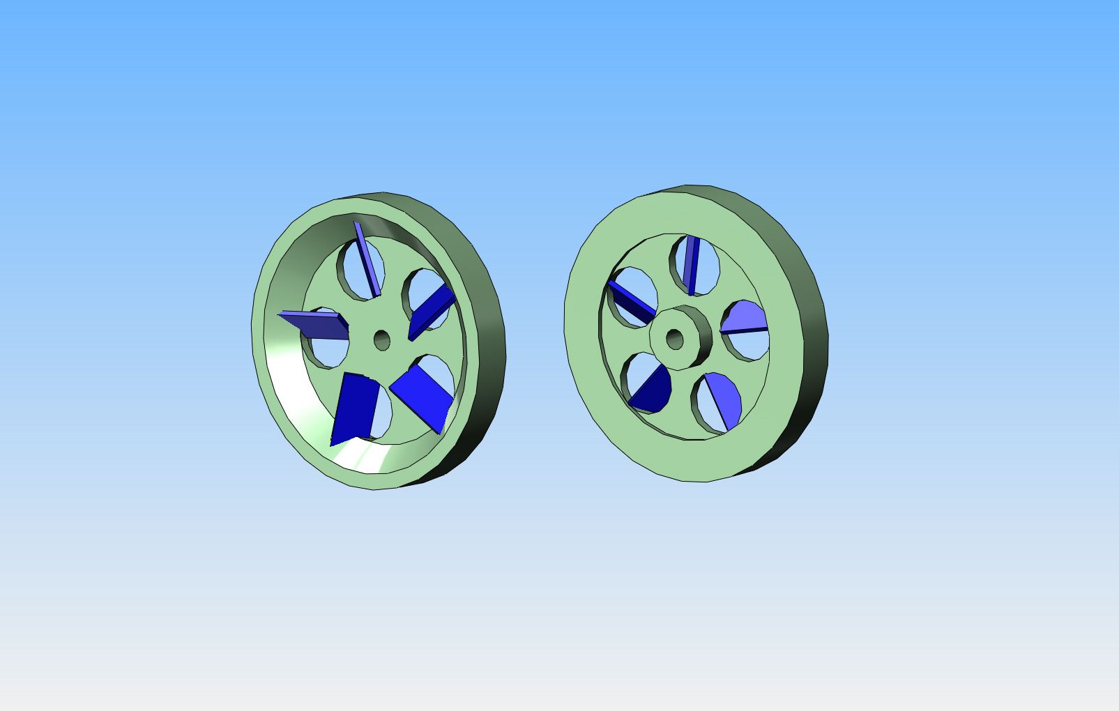
 The flywheel shown is 7" diameter, which is about 1" too much in my opinion, to keep the proportions reasonable.----So----Why make the flywheel so big?--Because a second factor I have proven to myself, is that without some kind of airflow over the fins, the engine will rapidly overheat. All you guys who build these small engines with a propeller, like for instance the Nemett series by Malcolm Stride will know how much the air from the prop will cool the engines. I don't like propellers.---Having once, in my jaded past, stuck a finger into a (thankfully small) propeller on a model gas airplane, I HATE propellers. So---What to do?--I need a flywheel anyways, it has to be made from steel (can't afford brass) and I can weld steel. ----By making the flywheel 1" larger in diameter, and drilling 5 holes through the web, I can then make up 5 blades of .125" thick steel and weld them into the holes at a 45 degree angle. This will create lots of air movement, yet the flywheel will have a smooth outer rim in case some poor fool like me inadvertantly touches it.  It will work. In fact, I think it will work very well. The only downside is that it makes the engine look "goofy".


Offline Brian Rupnow

  • Full Member
  • ***
  • Posts: 228
Re: Side Valve i.c. engine from Bar stock
« Reply #19 on: August 04, 2014, 01:12:33 PM »
GOOFY???

Offline Brian Rupnow

  • Full Member
  • ***
  • Posts: 228
Re: Side Valve i.c. engine from Bar stock
« Reply #20 on: August 04, 2014, 01:52:45 PM »
This is a very good example of engine size comparisons. The engine on the left is patterned after the Nemett Jagauar, an engine having a 7/8" bore and a 3" diameter flywheel. The engine on the right is my new side valve engine with a 1" bore and a 7" diameter flywheel.  The basic engines are very close to the same size. The new engine with the large flywheel has to have the support angle feet extended a long ways so the bottom of the flywheel will clear the table. Of course, I had to add a belt driven fan to the Nemett engine to get it to run cool enough, so it was extra work to make the fan, fan housing, blade, shaft, bushings, etcetera. I like the proportions of the Nemett engine a lot better.--Decisions--decisions---

Offline tom osselton

  • Hero Member
  • *****
  • Posts: 1255
  • Country: ca
Re: Side Valve i.c. engine from Bar stock
« Reply #21 on: August 04, 2014, 03:46:11 PM »
Somewhere on this site there is a pic of a flywheel offset and driven from a belt on the crank that would seperate the two making it look more pleasing.

Offline Brian Rupnow

  • Full Member
  • ***
  • Posts: 228
Re: Side Valve i.c. engine from Bar stock
« Reply #22 on: August 04, 2014, 04:59:51 PM »
As I have said before, I plan on using "sealed" roller (not ball) bearings on both ends of the con rod and "sealed' ball bearings on the load bearing side of the crankshaft. That is why the crank is split into two halves. Since the bearings are filled with grease and "sealed" I shouldn't have to lubricate the rod nor the crankshaft bearings. The more I look at it, the uglier it gets with that big flywheel on it.--I'm not too concerned about the airflow---the airflow hitting against the side of the crankcase will be forced out to the sides and "up and over" the cooling fins. I think I will probably go with a 4" diameter flywheel and a separate fan setting above it. That simplifies the flywheel by an order of magnitude, and I can probably utilize the computer fan/propeller that I bought for the Jaguar and then didn't use, driving it with an o-ring drive belt.--That will also direct more of the air across the cylinder and head.

Offline vtsteam

  • Global Moderator
  • Hero Member
  • *****
  • Posts: 6463
  • Country: us
  • Republic of Vermont
Re: Side Valve i.c. engine from Bar stock
« Reply #23 on: August 04, 2014, 08:59:10 PM »
Hmmm, I wouldn't want to get my finger caught in a flywheel either.
I love it when a Plan B comes together!
Steve
https://www.youtube.com/watch?v=4sDubB0-REg

Offline Brian Rupnow

  • Full Member
  • ***
  • Posts: 228
Re: Side Valve i.c. engine from Bar stock
« Reply #24 on: August 04, 2014, 09:26:20 PM »
I have a few minor logistics to figure out yet, but here is the engine with a 4" diameter flywheel and the 2 15/16" diameter computer fan I bought for a previous engine and then didn't use. As far as I'm concerned, this is a really big improvement over the 7" flywheel/fan.